Flat cable

a flat cable and cable technology, applied in the field of flat cables, can solve the problems of difficult coaxial cable, etc., and achieve the effect of preventing raveling, ensuring pitch accuracy, and easily and surely achieving complex and troublesome electric connection

Inactive Publication Date: 2010-08-10
JUNKOSHA
View PDF4 Cites 4 Cited by
  • Summary
  • Abstract
  • Description
  • Claims
  • Application Information

AI Technical Summary

Benefits of technology

[0006]The present invention has been made in view of various problems mentioned above, and it is an object of the present invention to provide a flat cable which makes it possible to well keep the pitch accuracy among a plurality of coaxial cables of the flat cable, and prevent separation of the outer conductors of the coaxial cables at the time of performing a complex and troublesome end process for the flat cable of the aforementioned kind, and makes it possible to keep the individual coaxial cables at predetermined positions, keep the pitch accuracy, and easily and surely achieve complex and troublesome connection even at the tip portions of the coaxial cables.
[0008]Accordingly, a plurality of coaxial cables exposed at an end portion of the flat cable by the cable end process have their middle portions, fixed to the sheet, made to remain in a band shape. This makes it difficult for the coaxial cables to be separated part at the end portion of the flat cable, and making it possible to well keep the pitch accuracy among the coaxial cables and easily and surely achieve complex and troublesome electric connection.
[0009]It is characterized in that the coaxial cables on the band-shaped sheet has not been subjected to a cable end process. Accordingly, the jackets of a plurality of exposed coaxial cables at the band-shaped sheet portion are kept fixed to the band-shaped sheet portion, thus making it possible to put the coaxial cables together at the end portion of the flat cable.
[0010]It is characterized in that the a dielectric layer of the coaxial cable, or the dielectric layer and a center conductor are exposed between the band-shaped sheet and a distal end of the flat cable, and a shield layer of the coaxial cable is exposed between the band-shaped sheet and a machined edge portion of the flat cable edge-machined portion. This makes it possible to prevent raveling of multiple laterally wound narrow conductive wires which form the shield layer.
[0011]It is characterized in that a metal bar for connection to the shield layer is connected between the band-shaped sheet and the machined edge portion of the flat cable edge-machined portion for collective grounding. Accordingly, the metal bar can be easily disposed at a predetermined position between the band-shaped sheet and the machined edge portion of the flat cable edge-machined portion by the guide function therebetween, thereby making it possible to easily and surely achieve ground connection of the shield layer.

Problems solved by technology

This makes it difficult for the coaxial cables to be separated part at the end portion of the flat cable, and making it possible to well keep the pitch accuracy among the coaxial cables and easily and surely achieve complex and troublesome electric connection.

Method used


Image

  • Flat cable
  • Flat cable
  • Flat cable

Examples


example

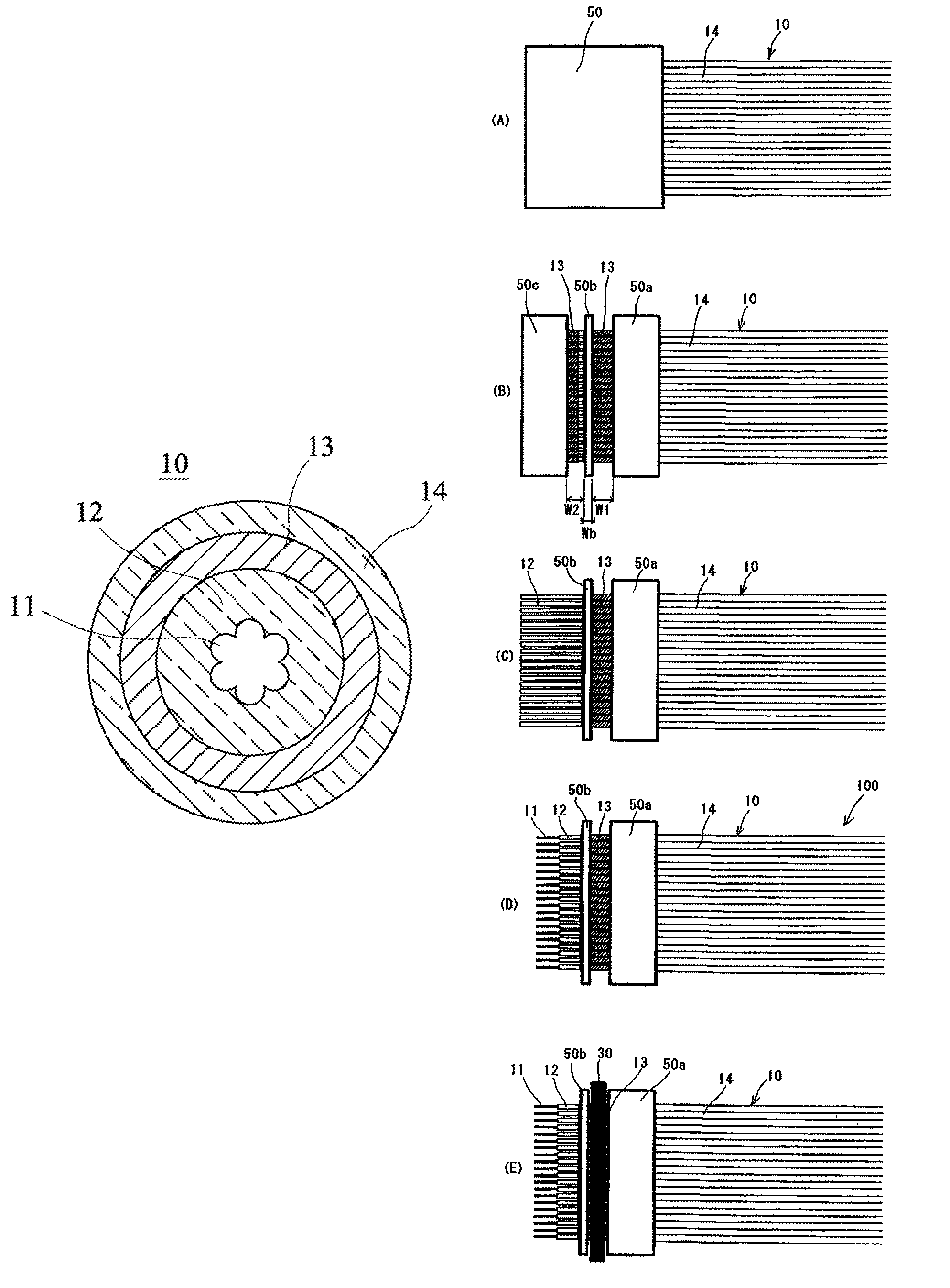
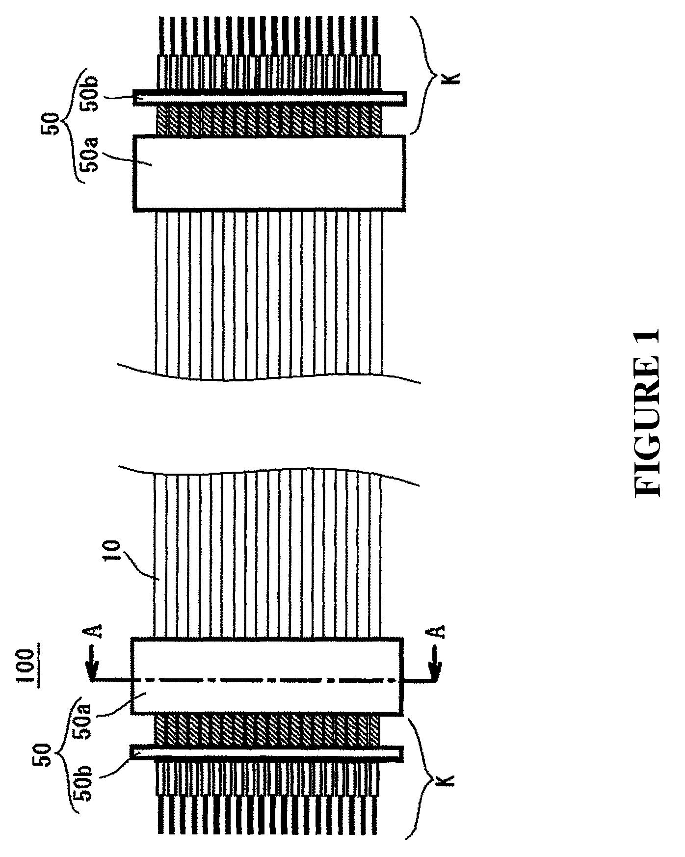
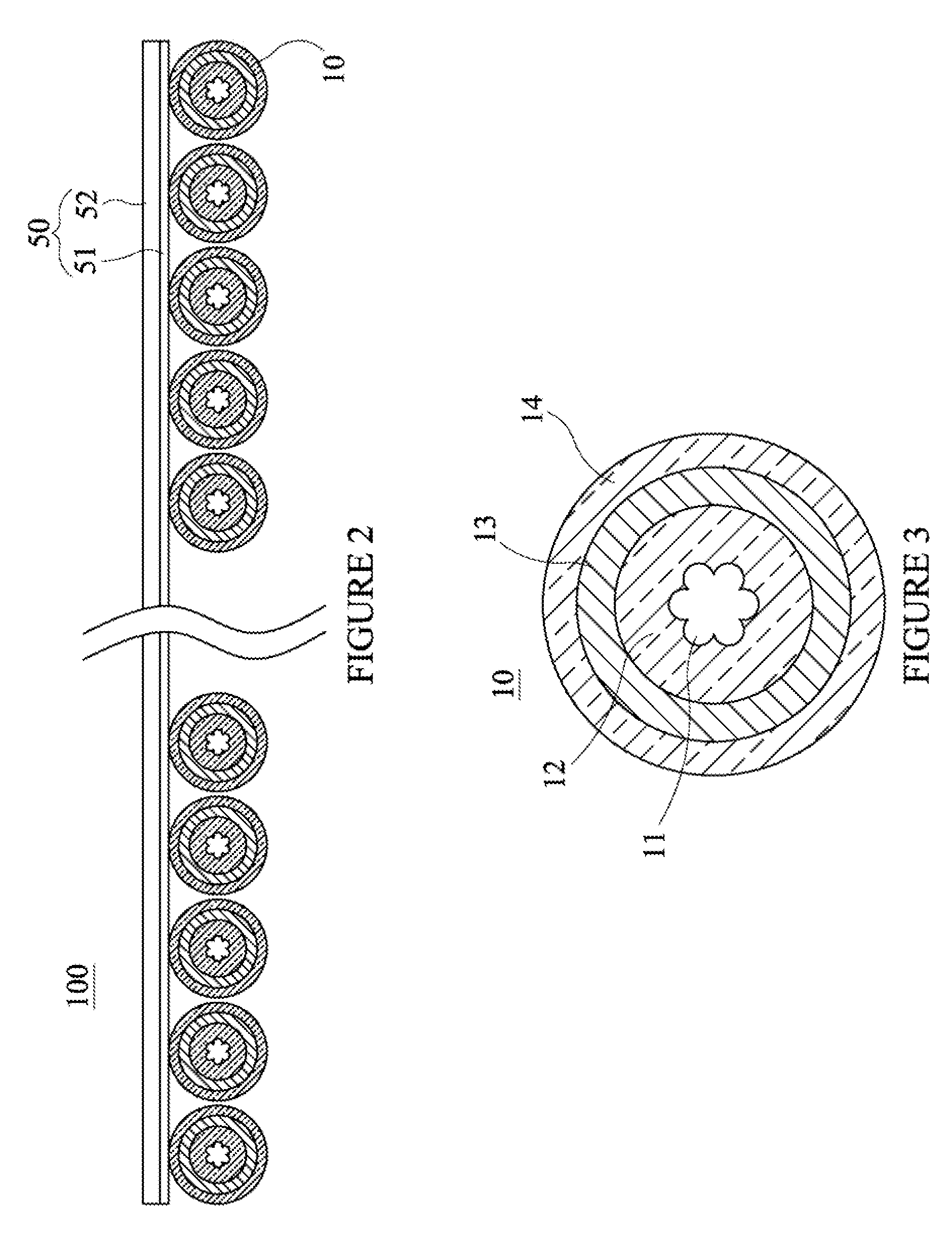
[0035]The flat cable 100 was prepared by providing the dielectric layer 12 of PFA with a thickness of about 50 μm around the outer surface of the center conductor 11 having stranded seven conductors with a diameter of 25 μm, winding 20 conductive wires with a diameter of 30 μm around the outer surface of the dielectric layer 12 to form the laterally wound shield layer 13 as an external conductive layer, and fixing 40 ultrathin coaxial cables 10 each having the jacket 14 of PFA with a thickness of about 35 μm provided on the outer surface of the shield layer 13, at cable pitches of 0.4 mm, only one side with the laminate sheets 50a, 50b of EPTFE having a thickness of 80 μm. Such a flat cable 100 could prevent the individual coaxial cables 10 from raveling apart at the time cable edge machining was executed for signal line connection and ground connection of the center conductors 11 of the individual coaxial cables to, for example, the contacts or the like of a connector, so that the ...


PUM

PropertyMeasurementUnit
diameteraaaaaaaaaa
diameteraaaaaaaaaa
diameteraaaaaaaaaa

Abstract

A flat cable in which at least end portions of a plurality of coaxial cables are securely arranged in parallel on a sheet is characterized in that a flat cable edge-machined portion for electric connection of the coaxial cables is formed at the end portion of the plurality of coaxial cables, and a part of the sheet is made to remain in a band shape across an entire width of the flat cable between a machined edge portion of the edge-machined portion and a distal end of the flat cable, and a jacket of the coaxial cable is secured to the band-shaped sheet.

Description

TECHNICAL FIELD[0001]The present invention relates to a flat cable having a plurality of coaxial cables arranged in parallel on a sheet.BACKGROUND ART[0002]A coaxial cable comprising a center conductor covered with a dielectric layer whose outer surface is covered with a shield layer having a conductive wire, and a covering (jacket) covering the outer surface of the shield layer is generally known and is widely used as a high-frequency transmission line. Recently, diameter of the coaxial cable is becoming narrower; for example, a very narrow coaxial cable whose center conductor has a diameter of 0.1 mm or less and whose outer surface has a diameter of about 0.35 mm is being used in electronic devices, such as a compact notebook type personal computer and a cellular phone.[0003]In those electronic devices, for example, a plurality of coaxial cables are used to electrically connect the liquid crystal display section of a notebook type personal computer to the main body portion thereof...

Claims


Application Information

Patent Timeline
Patent Type & Authority Patents(United States)
IPC IPC(8): H01B7/00
CPCH01B7/0823H01B11/203H01B7/17
Inventor MORIJIRI, DAISUKE
Owner JUNKOSHA
Why Eureka
Try Eureka