
Laser processing method and laser processing apparatus

a laser processing and laser processing technology, applied in metal working equipment, manufacturing tools, welding/soldering/cutting articles, etc., can solve the problems of increasing the change in the speed of the table, slowing down the overall processing speed, and affecting the accuracy of finishing, so as to accelerate the processing speed and maintain the effect of finishing accuracy

Active Publication Date: 2019-07-16
HITACHI SEIKO LTD
View PDF15 Cites 0 Cited by
  • Summary
  • Abstract
  • Description
  • Claims
  • Application Information

AI Technical Summary

Benefits of technology

[0006]The object of the present invention is to achieve the combination processing that accelerates the processing speed while keeping the accuracy of finishing.
[0012]According to the present invention, it is possible to achieve the combination processing that accelerates the processing speed while keeping the accuracy of finishing.

Problems solved by technology

If the density of hole in an area is extremely low, however, it is difficult to move the table within the time period for the laser scanning in the area, which may necessitate a halt in the laser scanning and slow down the overall processing speed.
In addition, when the synchronization processing in an area having an extremely low density of holes is followed by the stationary processing, or in the opposite case, the state of the table should be transferred from a high-speed moving state to a stationary state, or in the opposite direction, which increases the change in the speed of the table and makes it difficult to keep the accuracy of finishing.
As a result of this, if the processing speed is intended to be accelerated by increasing the speed of the table, it will increase the change in the speed of the table and make it difficult to keep the accuracy of finishing.

Method used


Image

  • Laser processing method and laser processing apparatus
  • Laser processing method and laser processing apparatus
  • Laser processing method and laser processing apparatus

Examples


first embodiment

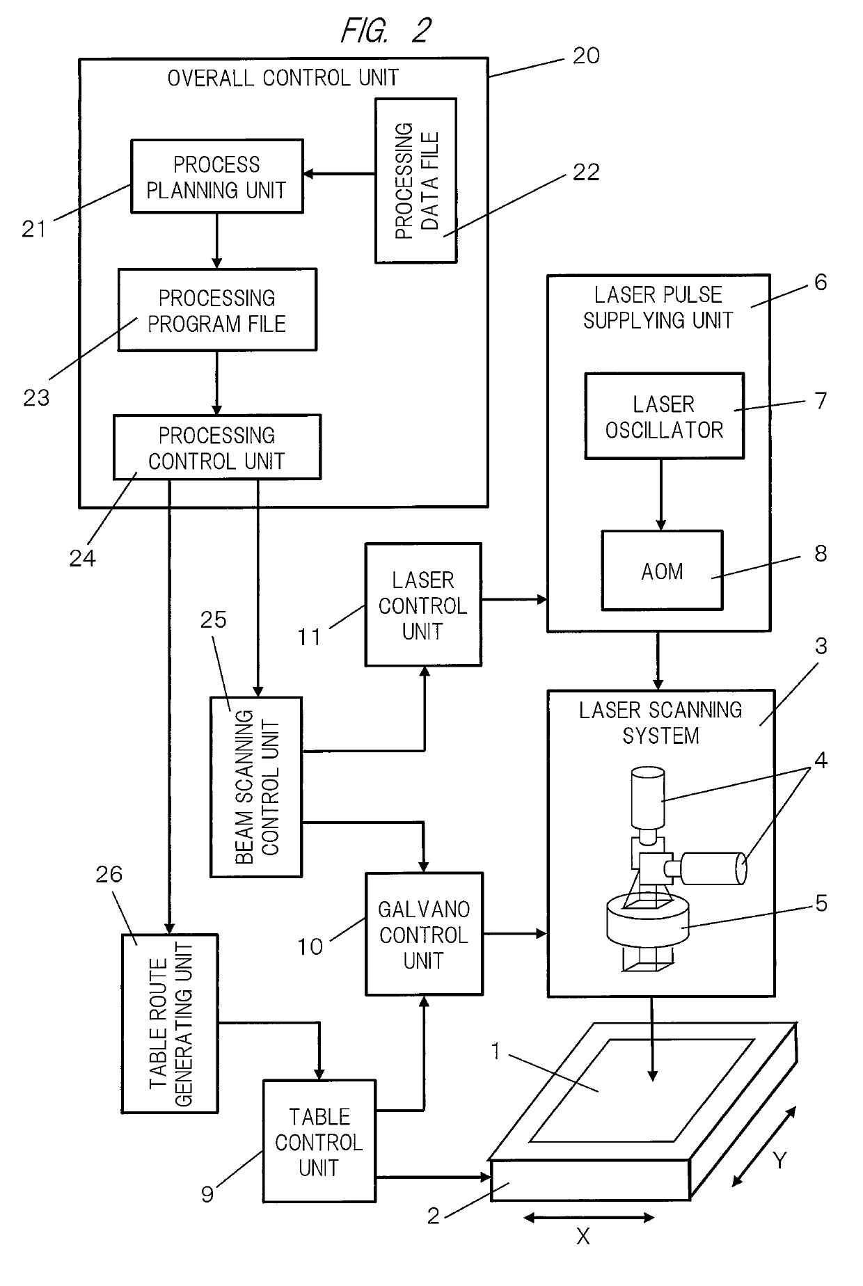
[0027]The first embodiment of the present invention will now be described. FIG. 2 is a block diagram illustrating the laser processing apparatus for making holes according to the first embodiment of the invention. FIG. 2 illustrates the following elements. A printed-circuit board 1 is subjected to the processing for making holes, a table 2 holds the printed-circuit board 1 mounted on the table 2, and a laser scanning system 3 adjusts and moves the irradiation position of laser pulses. The laser scanning system 3 includes a pair of Galvano scanners 4 and condensing (fθ) lenses 5 for the X-axis and the Y-axis. A laser pulse supplying system 6 supplies laser pulses to the laser scanning system 3. The laser pulse supplying system 6 includes a laser oscillator 7 for generating laser pulses and an acousto-optic modulator (AOM) 8 for controlling the output of laser pulses to the laser scanning system 3 by branching control. A pair of table control units 9 controls the position of the table...

second embodiment

[0068]The second embodiment of the present embodiment will now be described.

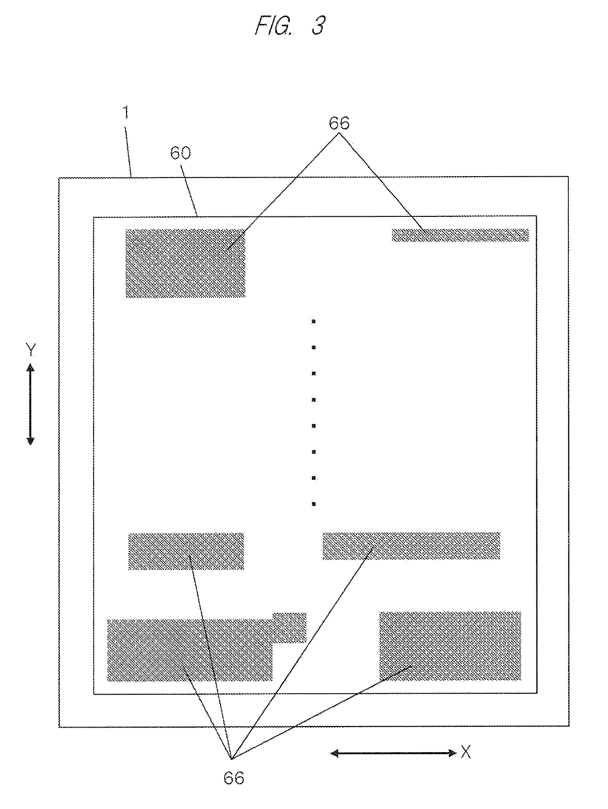
[0069]Generally, a typical printed-circuit board has a processing area 60 having a low density of holes in a circumferential area. In addition, in a not-to-be-processed band area, the density of holes often becomes lower not rapidly but gradually. When the sections with a predetermined area are sequentially determined in the processing area 60 as described above, as illustrated in FIG. 13A, the leftmost section series band area 63 in the first row at the bottom in FIGS. 5 and 6 is more likely to have a hole zone 66 with a small number of holes in the section 631 at the left end (at the starting point) near the inner circumferential area of the processing area 60 and in the section 632 at the ending point just before the next not-to-be-processed band area. As illustrated in FIG. 13B, the rightmost section series band area 63 in the first row at the bottom is more likely to have a hole zone 66 with a small num...

third embodiment

[0074]The third embodiment of the present invention will now be described.

[0075]In the third embodiment, the first embodiment is modified as follows. As illustrated in FIG. 14A, in a certain row 62, if sections 635 having the stationary processing attributes are positioned in continuous series and the number of the sections 635 exceeds a predetermined number, as illustrated in FIG. 14B, a new logical section 636 having area size consisting of two continuous sections 636 (hereinafter a double section), which has area equal to the scanning area, is assigned one by one and performed processing.

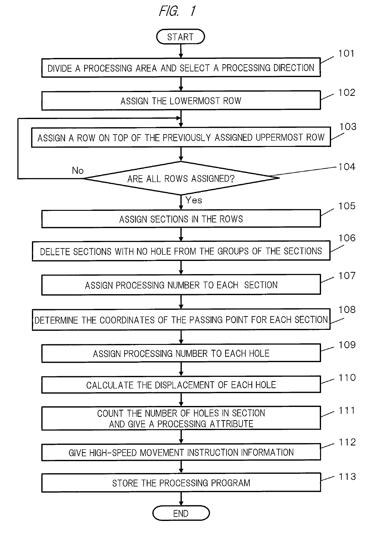
[0076]This third embodiment can be embodied by adding the following steps (1) to (6) to the flow chart of FIG. 1 illustrating the operation of the process planning unit 21 of FIG. 2.

[0077](1) After giving processing attributes at steps 111 and 112 in FIG. 1, when sections having the stationary processing attributes are positioned continuously viewed from the left end in each row, the process plan...


PUM

PropertyMeasurementUnit
areaaaaaaaaaaa
band areaaaaaaaaaaa
relative movementaaaaaaaaaa

Abstract

The object of the present invention is to achieve the combination processing that accelerates the processing speed while keeping the accuracy of finishing. In the combination processing consisting combination of stationary processing and synchronization processing, the processing of the section in the rows in an processing area is performed from a first end to a second end of a row, and then from the second end to the first end of the next row so that the processing is performed from side to side. The stationary processing is performed in sections having relatively low processing densities and the synchronization processing is performed in the other sections than the sections for the stationary processing.

Description

CROSS-REFERENCE TO RELATED APPLICATION[0001]The present application claims priority from Japanese Patent Application No. 2016-015693 filed on Jan. 29, 2016, the content of which is hereby incorporated by reference into this application.TECHNICAL FIELD OF THE INVENTION[0002]The present invention relates to a laser processing method and a laser processing apparatus for making holes at a plurality of positions in a workpiece such as a printed-circuit board by laser scanning.BACKGROUND OF THE INVENTION[0003]As the examples of laser processing method for making holes, there are a processing method (hereinafter, called “stationary processing”) in which laser scanning is performed on a workpiece mounted on a stationary table, and another processing method (hereinafter, called “synchronization processing”) in which laser scanning is performed on a workpiece mounted on a table while moving the table in order to accelerate the processing speed.[0004]Japanese Patent No. 3561159, Patent Laid-Op...

Claims


Application Information

Patent Timeline
Patent Type & Authority Patents(United States)
IPC IPC(8): B23K26/035B23K26/08B23K26/402B23K26/082B23K26/0622B23K26/382B23K101/36B23K101/42
CPCB23K26/035B23K26/0622B23K26/082B23K26/382B23K26/402B23K26/0853B23K2101/42B23K2101/36B23K26/0643H05K3/0026
Inventor OTSUKI, HARUAKISUZUKI, KYOSUKEFUKUSHIMA, SATOSHI
Owner HITACHI SEIKO LTD
Learn More