Catheter with side sheath and methods

a side sheath and catheter technology, applied in the field of catheter systems, can solve the problems of limiting the ability to insert a branch stent into the side, compromising the patency of the main vessel and/or its branches, and generally produced in a straight tubular configuration, so as to facilitate the attachment of syringes and hinder the preparation of the device for use.

Inactive Publication Date: 2010-08-10
BOSTON SCI SCIMED INC
View PDF479 Cites 57 Cited by
  • Summary
  • Abstract
  • Description
  • Claims
  • Application Information

AI Technical Summary

Benefits of technology

[0011]In one aspect, such a catheter system facilitates placement of the stent within the main vessel, with the side hole being in registry with an ostium of a branch vessel. This may be accomplished, for example, by advancing a main vessel guidewire in the main vessel until passing the branch vessel. The catheter is then advanced over the main vessel guidewire until the stent reaches or is proximal to the branch vessel. At this point, a branch vessel guidewire may be introduced through the branch vessel lumen of the side member. The branch vessel guidewire is advanced out of the side member and into the branch vessel to assist in aligning the side hole with the ostium of the branch vessel prior to deployment of the stent in the main vessel. To assist in guiding the branch vessel guidewire into the branch vessel, the side member may taper to a narrow distal end, which may also be curved slightly outwardly. One advantage of such a catheter system is that a single guidewire may be used to introduce the catheter. The catheter then serves as a guide for the branch vessel guidewire.
[0013]Alignment of the side hole with the ostium may be accomplished in a variety of ways. For example, introduction of the branch vessel guidewire into the branch vessel may sufficiently align the side hole with the ostium. Other alignment techniques may depend on the configuration of the side member. For example, in some cases the side member may comprise a flexible sheath that is movably coupled to the catheter body, e.g., by passing through a lumen of a truncated connector that is coupled to the catheter body. Once the branch vessel guidewire is advanced into the branch vessel, the sheath may be advanced into the branch vessel to move the side hole into registry with the ostium. Conveniently, the catheter body and the side member may be fabricated from pebax and graphite to facilitate relative movement between the catheter body and the side member.
[0016]Such relative movement of the radiopaque markers may be viewed as a rotation of a marker positioned on the side member with respect to one or more markers positioned on the catheter body, or as a separation between the marker on the side member with respect to one or more markers on the main catheter. In one aspect, markers may be positioned at the distal ends of the side member and the catheter body, such that the separation between these markers will be relatively large, and thus can be easily viewed. Moreover, when the markers are positioned at the distal ends of the main vessel stent and side member, the surgeon will view the separation of these markers earlier than would be the case if these markers were disposed at a more proximal location.
[0020]In another aspect, the catheter system may be used to deploy a branch vessel stent within the branch vessel following deployment of the main vessel stent. A variety of techniques may be used to deploy the branch vessel stent. For example, if the side member is slidably coupled to the catheter body, the side member may be provided with a balloon at the distal end, with the branch stent being coupled over the balloon. In this way, the side member may be advanced into the branch vessel and the balloon inflated to deploy the branch stent. As another example, the side member may be retracted from the main vessel while the branch vessel guidewire is kept in place. A stent deployment device having a balloon and a branch stent disposed over the balloon may then be advanced over the branch guidewire and into the branch stent. The branch stent may then be deployed by inflating the balloon. In another option, the main vessel stent may be only partially expanded to permit the branch stent to be deployed through the main vessel stent. Once the branch vessel stent is in place, the main vessel stent may be fully deployed.
[0022]In one particular aspect, the catheter system may further include a proximal end hub having a main vessel guidewire channel that is coupled to the main vessel guidewire lumen, a branch vessel guidewire channel that is coupled to the branch vessel guidewire lumen, and a balloon inflation port that is coupled to the balloon inflation lumen. In one aspect, the first and second guidewire channels may be separated by about zero to about 20° to aid wire movement without hindering device preparation for use. For example, such an angle facilitates the attachment of syringes while also ensuring that the guidewires are not too separated.

Problems solved by technology

One of the drawbacks of conventional stents is that they are generally produced in a straight tubular configuration.
The use of such stents to treat diseased vessels at or near a bifurcation (branch point) of a vessel may create a risk of compromising the degree of patency of the main vessel and / or its branches, or the bifurcation point and also limits the ability to insert a branch stent into the side branch if the result of treatment of the main, or main, vessel is suboptimal.
As will be appreciated, such tasks may be challenging.
For example, management of two guidewires used in introducing and / or orienting stents can pose particular challenges, such as the tendency of the guidewires to twist together.
As another example, imaging placement of the stents using low-cost and convenient techniques, such as x-ray or ultrasound imaging, can be difficult using existing methods.

Method used


Image

  • Catheter with side sheath and methods
  • Catheter with side sheath and methods
  • Catheter with side sheath and methods

Examples


Embodiment Construction

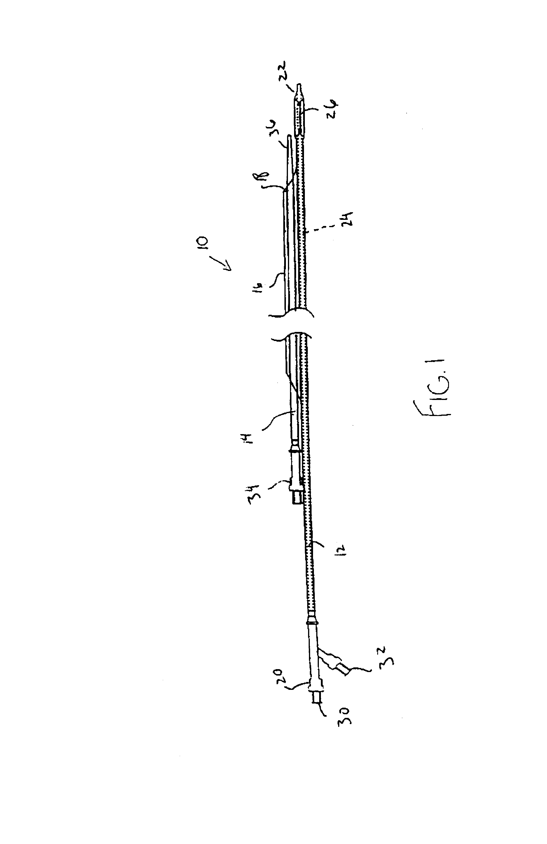
[0049]The present invention provides systems and methods for positioning a pair of guidewires in main and branch vessels at a vessel bifurcation to facilitate positioning and deployment of one or more stents, such as a main vessel stent or a branch vessel stent. The systems and methods may also be used to align a side hole in a main vessel stent in registry with the ostium of a branch vessel.

[0050]Applications of the invention include the cardiac, coronary, renal, peripheral vascular, gastrointestinal, pulmonary, urinary and neurovascular systems and the brain. Advantages of the invention include, but are not limited to, the use of an improved stent delivery apparatus, which may deliver main vessel and branch vessel stents to: 1) completely cover the bifurcation point of bifurcation vessels; 2) be used to treat lesions in one branch of a bifurcation while preserving access to the other branch for future treatment; 3) allow for differential sizing of the stents in a bifurcated stent ...


PUM


Abstract

A catheter system comprises a catheter having a catheter body with a distal end, a proximal end, a main vessel guidewire lumen for receiving a main vessel guidewire and a balloon disposing at the distal end of the catheter body. The catheter further includes a side member that is disposed adjacent to the catheter body. The side member has a distal end, a proximal end, and a branch vessel guidewire lumen for receiving a branch vessel guidewire. A stent having a side hole is disposed over the balloon, and a distal portion of the side member is disposed beneath at least a portion of the stent while being adjacent to and movable with respect to the balloon.

Description

CROSS-REFERENCES TO RELATED APPLICATIONS[0001]This application is a continuation-in-part of U.S. patent application Ser. No. 09 / 614,472, filed Jul. 11, 2000, and entitled “CATHETER WITH SIDE SHEATH” (abandoned), which is a continuation-in-part of U.S. patent application Ser. No. 09 / 325,996, filed Jun. 4, 1999, and entitled “CATHETER WITH SIDE SHEATH” (abandoned), and which is a continuation-in-part of U.S. patent application Ser. No. 09 / 455,299, filed Dec. 6, 1999, and entitled “CATHETER WITH ATTACHED FLEXIBLE SIDE SHEATH,” (now U.S. Pat. No. 6,692,483), the disclosures of which are herein incorporated by reference.[0002]This application also is a continuation-in-part of U.S. patent application Ser. No. 09 / 455,299, filed Dec. 6, 1999, and entitled “CATHETER WITH ATTACHED FLEXIBLE SIDE SHEATH” (now U.S. Pat. No. 6,692,483).[0003]This application claims priority to said Ser. Nos. 09 / 614,472; 09 / 325,996; and 09 / 455,299 to the extent appropriate by law.TECHNICAL FIELD[0004]The present i...

Claims


Application Information

Patent Timeline
IPC IPC(8): A61F2/06A61F2/00A61F2/82A61M25/00A61M25/01A61M25/098
CPCA61F2/954A61F2/958A61M25/0116A61F2/064A61F2/07A61F2/856A61F2002/821A61F2250/006A61F2250/0098A61M2025/0177A61M2025/1045
Inventor DAVIDSON, CHARLES J.VARDI, GIL M.WILLIAMS, ERIC
Owner BOSTON SCI SCIMED INC
Why Eureka
Try Eureka