
Portable swing speed analyzer

a portable, speed analyzer technology, applied in the field of sports equipment, to achieve the effect of improving the accuracy with which the swing speed analyzer measures acceleration

Inactive Publication Date: 2010-08-10
TELFORD GOLF ENTERPRISES
View PDF13 Cites 124 Cited by
  • Summary
  • Abstract
  • Description
  • Claims
  • Application Information

AI Technical Summary

Benefits of technology

"The present invention is a swing speed analyzer that uses an accelerometer to measure the speed of a swinging implement, such as a golf club, when it strikes an object. The accelerometer is detachably mounted on the implement and is designed to isolate from high shock forces. The analyzer can measure either centrifugal acceleration or tangential acceleration, depending on the type of implement. The measurement of centrifugal acceleration is used to determine the maximum velocity of the swinging implement, while the measurement of tangential acceleration is used to account for additional velocity caused by the flexing of the implement. The analyzer is calibrated for a specific implement and can extract useful data from the acceleration measurements. It also includes a dual-axis accelerometer that measures both components of tangential acceleration in the direction of movement, allowing for the accurate measurement of tangential velocity and distance traveled by the swinging implement. The analyzer can display various swing parameters, such as duration of the forward swing and distance traveled by the swinging implement, for further analysis."

Problems solved by technology

However, because the swing speed analyzer may typically be used on a driver type golf club of a given shaft length and stiffness instead of on multiple golf clubs having different shaft lengths, any limitations in measurement accuracy caused by change in shaft length, the swing speed analyzer still allows a user to extract useful data from centrifugal acceleration measurements.

Method used


Image

  • Portable swing speed analyzer
  • Portable swing speed analyzer
  • Portable swing speed analyzer

Examples


Embodiment Construction

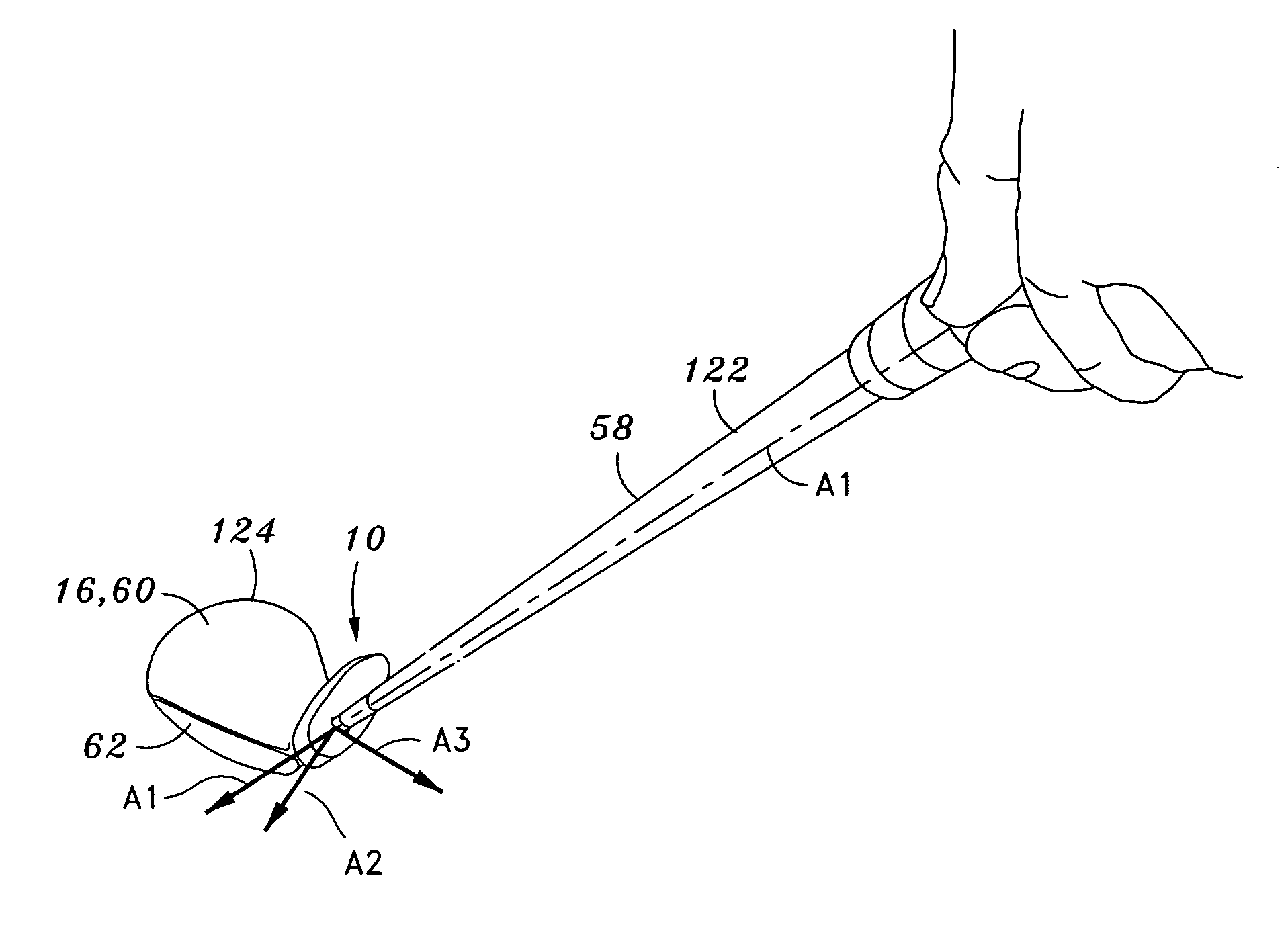
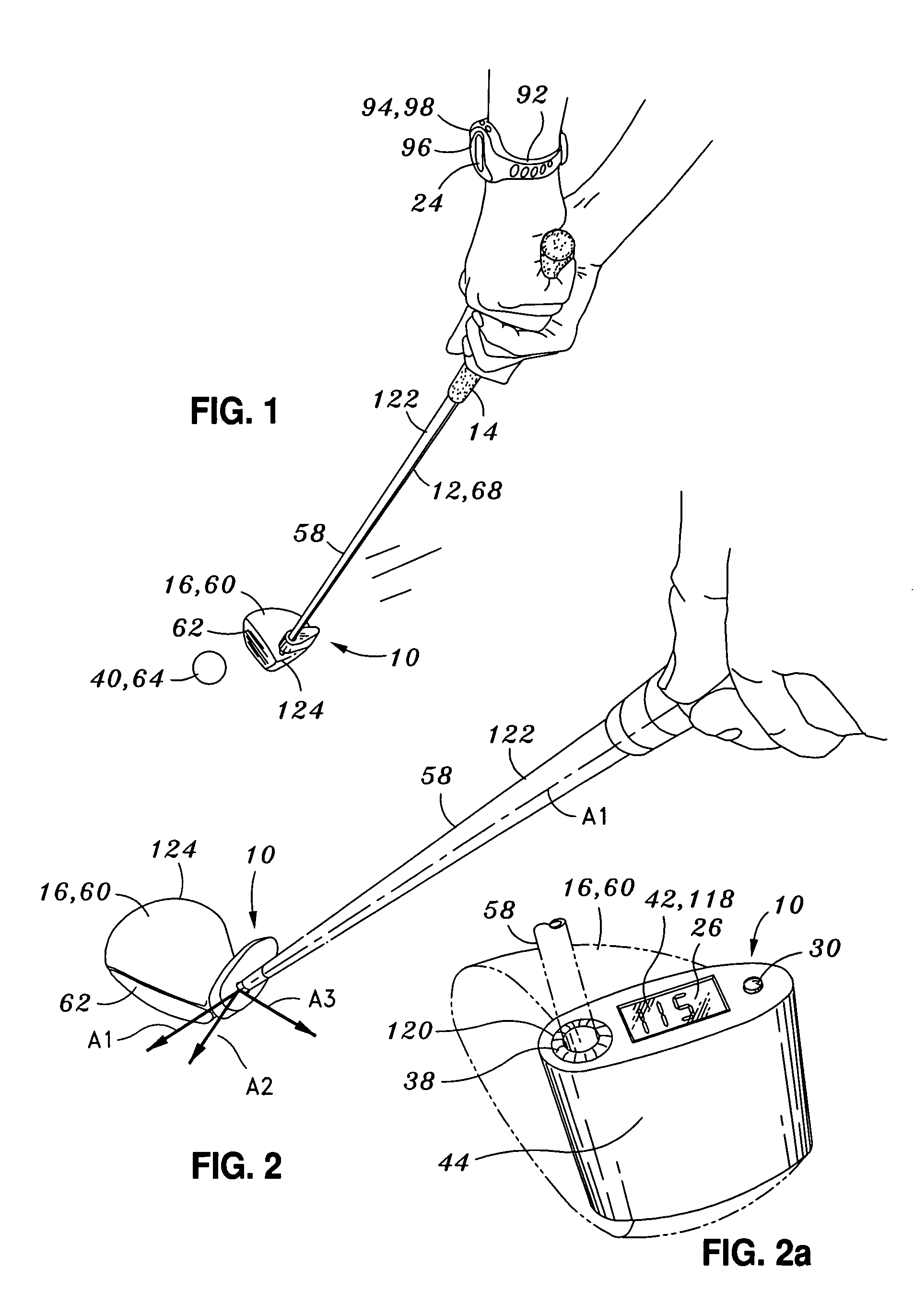
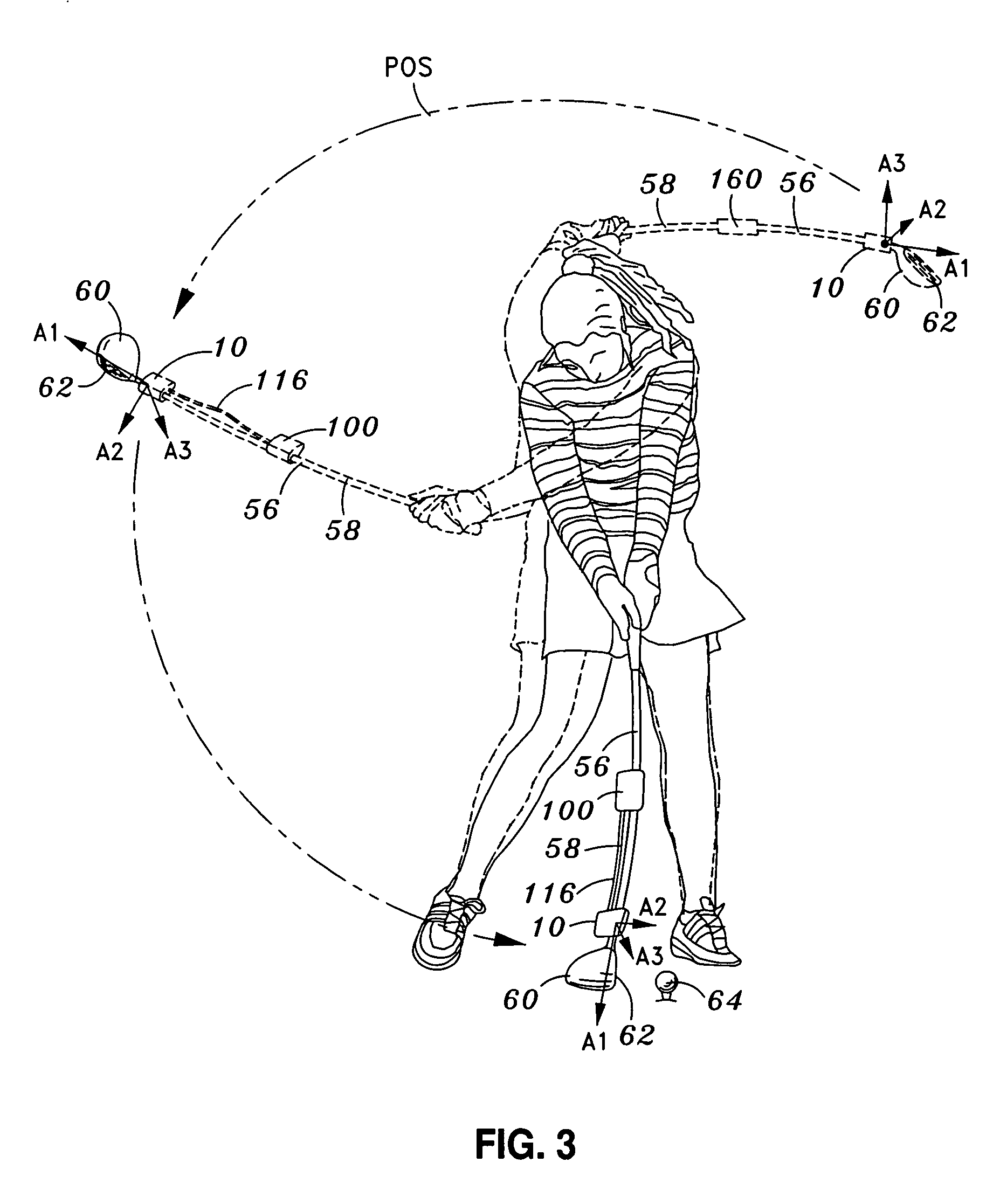
[0051]Referring now to the drawings wherein the showings are for purposes of illustrating various aspects of the invention and not for purposes of limiting the same, provided is a swing speed analyzer 10 as may be mounted on a swinging implement 12. The swing speed analyzer 10 is configured to measure a swing parameter during a forward swing of the swinging implement 12. As can be seen in FIGS. 1 and 2, the swinging implement 12 has a striking end 16 and a grip end 14 with the swing speed analyzer 10 preferably being mounted adjacent the striking end 16. The swing of the swinging implement 12 defines a plane of swing, indicated as POS in FIG. 3. The swinging implement 12 also defines a first axis A1 that extends therethrough from the grip end 14 to the striking end 16. The grip end 14 may be held or grasped by a user in swinging the swinging implement 12. The swing parameter may be measured during a swing of the swinging implement 12 wherein the striking end 16 may or may not strike...


PUM


Abstract

Provided is a swing speed analyzer for mounting on a swinging implement and comprising a first accelerometer, a processor and a shock attenuator. The processor uses an output from the first accelerometer to compute a swing speed of the swinging implement. The shock attenuator is comprised of a material that is sized and dimensioned to dampen an impact shock wave by more than 50% at 125 Hz. The material is preferably sized and dimensioned to dampen the impact shock wave from more than 1000 g to less than 500 g. Suitable attenuators can include viscoelastomeric materials such as foam. The swing speed analyzer can advantageously include any of a releasable attachment mechanism, a liquid crystal or other visual display, a second accelerometer, and a strain gauge. The analyzer can advantageously be attached to a golf club, a tennis racket, a baseball bat, or a hockey stick.

Description

CROSS-REFERENCE TO RELATED APPLICATIONS[0001](NOT APPLICABLE)STATEMENT RE: FEDERALLY SPONSORED RESEARCH / DEVELOPMENT[0002](NOT APPLICABLE)BACKGROUND OF THE INVENTION[0003]The present invention generally relates to sporting equipment and, more particularly, to a portable swing speed analyzer that is specifically adapted to be releasably mounted on a hand-held sporting implement such as a golf club. The swing speed analyzer is configured to measure swing parameters such as velocity during impact with an object such as a golf ball and to display the swing parameters on a display device. The swing speed analyzer may be further configured to measure bending in the hand-held sporting implements such as a golf club shaft, during a forward swing in order to determine whether potential energy resulting from bending of a golf club shaft is released at the instant when the golf club strikes the golf ball.[0004]Many sporting activities such as golf, tennis and baseball utilize a swinging impleme...

Claims


Application Information

Patent Timeline
Patent Type & Authority Patents(United States)
IPC IPC(8): A63F9/24G06F17/00A63B67/02A63F13/00G06F19/00
CPCA63B24/0003A63B69/3632A63B71/0622G01P1/023G01P3/22G01P15/00A63B59/0074A63B59/0092A63B69/0024A63B69/38A63B2069/0008A63B2071/0658A63B2071/0663A63B2220/20A63B2220/30A63B2220/40A63B2220/54A63B2220/62A63B2225/50A63B60/54A63B60/42A63B60/46
Inventor TELFORD, KENNETH N.
Owner TELFORD GOLF ENTERPRISES
Learn More