
Electrical connecting apparatus

a technology of connecting apparatus and electrical contacts, which is applied in the direction of electrical apparatus, coupling device connection, printed circuit, etc., can solve the problems of affecting interfering with the insulating housing, and increasing the normal force on the electrical contact, so as to ensure the reliability of the product

Inactive Publication Date: 2010-08-10
LOTES
View PDF13 Cites 8 Cited by
  • Summary
  • Abstract
  • Description
  • Claims
  • Application Information

AI Technical Summary

Benefits of technology

The present invention provides an electrical connecting apparatus that reduces interference between the electrical contact and the housing when the electrical contact makes contact with an electronic device. This is achieved by avoiding interference between the electrical contact and the housing by designing the electrical contact to move away from the rib when the contact portions make contact with the electronic device. The electrical contact has a base portion located underneath the rib and a gap is formed between the base portion and the rib. The electrical contact also has elastic clip arms that clip both sides of the rib and form opposite contact surfaces, which move away from each other when an electronic device inserts to the contact surfaces. This reduces the normal forces exerted on the electrical contact due to interference with the housing, ensuring the reliability of the product.

Problems solved by technology

Meanwhile, the elastic arm and the connecting portion press tightly both sides of the support block, respectively, so that the electrical contact interferes with the insulating housing and the normal force on the electrical contact is increased.
Thereby, the reliability of the product is affected.

Method used


Image

  • Electrical connecting apparatus
  • Electrical connecting apparatus
  • Electrical connecting apparatus

Examples


Embodiment Construction

[0018]In order to make the structure and characteristics as well as the effectiveness of the present invention to be further understood and recognized, the detailed description of the present invention is provided as follows along with preferred embodiments and accompanying figures.

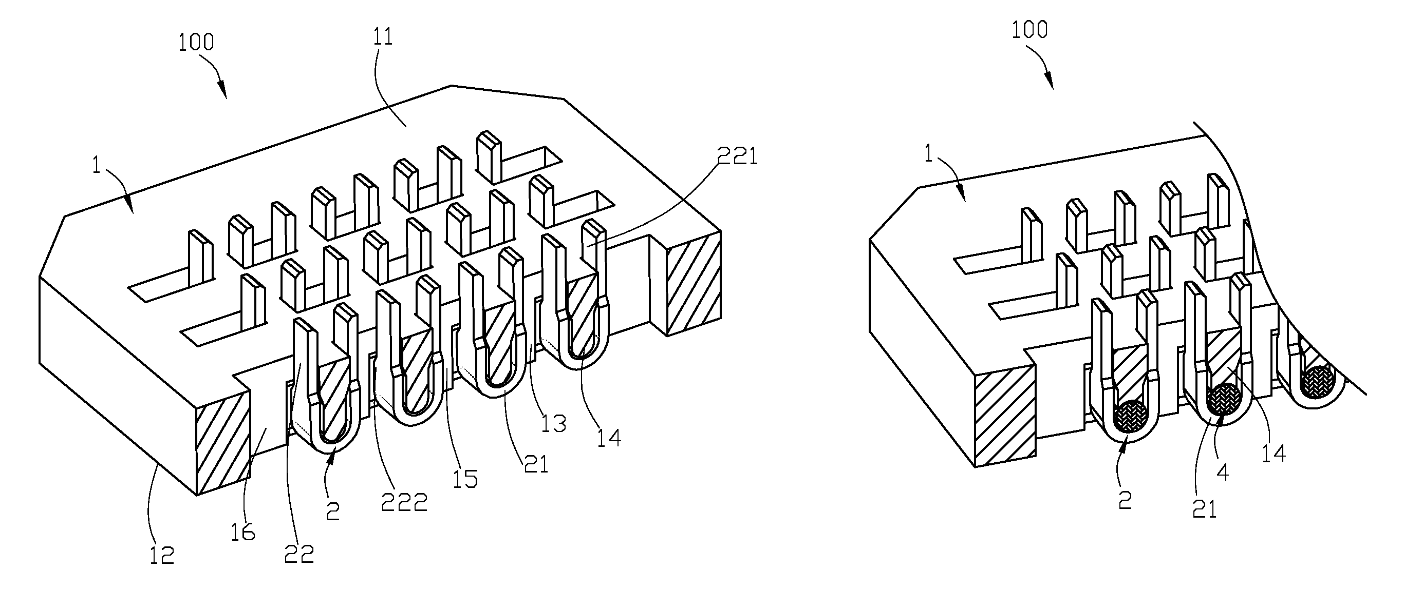
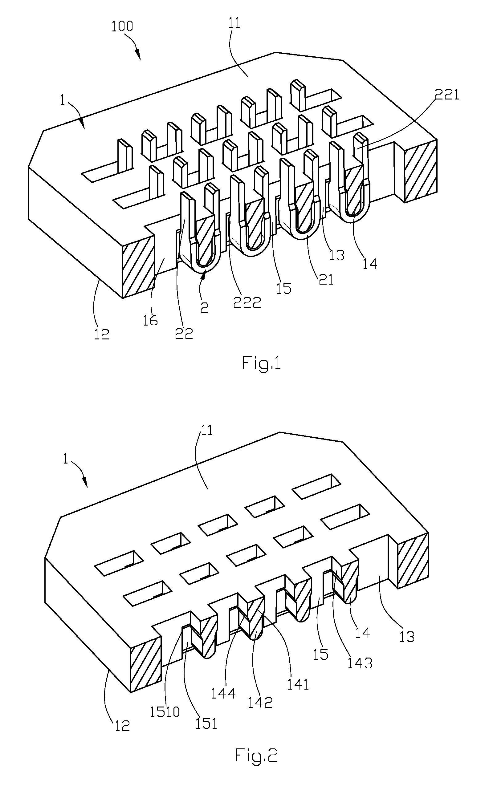
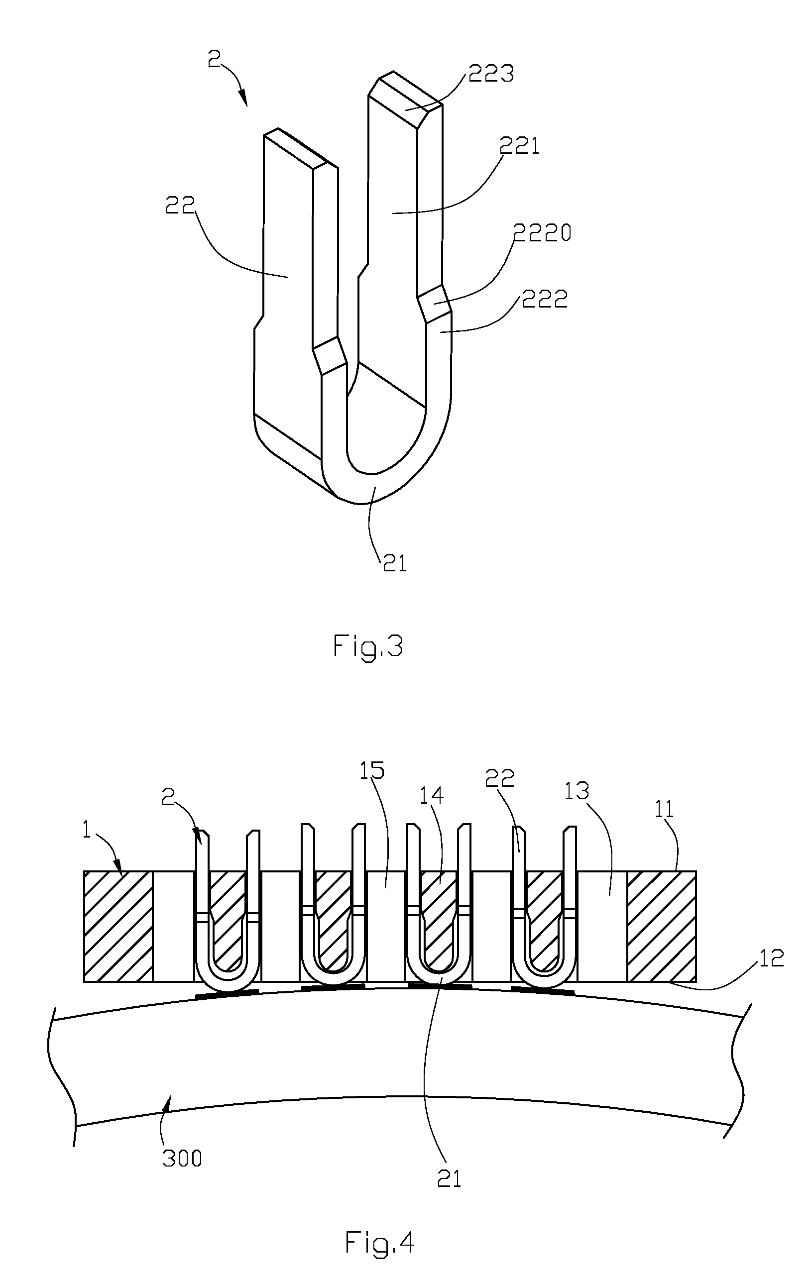
[0019]Please referring to FIG. 1 to FIG. 5 show the novel electrical connecting apparatus according to the first preferred embodiment of the present invention. The electrical connecting apparatus 100 according to the present invention is used for electrically connecting a chip module 200 to a circuit board 300, and comprises a housing 1 and a plurality of electrical contacts 2 held in the housing 1.

[0020]Please referring to FIG. 1 and FIG. 2, said housing 1 has a connection side 11 (which is, in fact, the top surface of the housing 1) close to the chip module 200, and an installation side 12 (which is, in fact, the bottom surface of the housing 1) opposite to the connection side 11 and close to the circui...


PUM


Abstract

The electrical connecting apparatus according to the present invention is used for providing electrical contacts for an electronic device and comprises a housing and a plurality of electrical contacts. At least one passageway is set on the housing. At least two ribs are set in the passageways. Within the passageways, at least one holding space is formed between two adjacent ribs. The electrical contacts are set in the passageways, respectively. In addition, portions of at least two electrical contacts are accommodated in the same holding space. The electrical contact has a base portion located underneath the rib. A pair of contact portions is formed by extending upwards from the base portion along corresponding two sides of the rib. Besides, at least one contact portion pass through the holding space. When the paired contact portions of each said electrical contact make contact with the electronic device, the contact portions move away from said rib. When the paired contact portions of each electrical contact of the electrical connecting apparatus according to the present invention make contact with an electronic device, the contact portions move away from said rib. Thereby, the electrical contact does not interfere with the housing. Consequently, the reliability of the product can be guaranteed.

Description

FIELD OF THE INVENTION[0001]The present invention relates to an electrical connecting apparatus.BACKGROUND OF THE INVENTION[0002]U.S. Pat. No. 6,447,304 discloses an electrical connecting apparatus comprising an insulating housing and a plurality of electrical contacts. The insulating housing has a plurality of passageways perpendicular to the surface of the insulating housing. A support block is set within the passageway. The electrical contact is received within the passageway, and comprises an elastic arm, a contact portion formed by bending and extending upwards from one end of the elastic arm, a connecting portion formed by bending and extending downwards from one end of the contact portion, and a soldering portion formed by extending downwards from one end of the connecting portion. The elastic arm and the connecting portion clip from both sides of the support block, respectively. When the electrical contact makes contact with an electronic device, the contact portion is force...

Claims


Application Information

Patent Timeline
Patent Type & Authority Patents(United States)
IPC IPC(8): H01R12/00
CPCH01R13/2407H01R13/2435H01R13/2457H01R13/2485H05K7/1084
Inventor CHANG, WEN-CHANG
Owner LOTES
Learn More