
System, method and apparatus for hydrogen-oxygen burner in downhole steam generator

a technology of hydrogen-oxygen burner and steam generator, which is applied in the direction of borehole/well accessories, combustion types, insulation, etc., can solve the problems of increasing the api gravity, difficult and expensive hydrocarbon recovery, and lowering the viscosity of hydrocarbon in situ, so as to improve the mobility of heavy crude oil held, increase the quality, and improve the effect of quality

Inactive Publication Date: 2010-08-10
WORLD ENERGY SYST
View PDF64 Cites 39 Cited by
  • Summary
  • Abstract
  • Description
  • Claims
  • Application Information

AI Technical Summary

Benefits of technology

"The patent describes a system for upgrading heavy crude oils in a steam generator. The system includes a downhole burner with an injector and cooling liner. Fuel, steam, and oxidizer are injected into the burner and combustion occurs within the cooling liner. The heated steam and combustion products are then directed into an oil-bearing formation to improve the quality of the heavy crude oil. The injector has a unique design with concentric rings for fuel and oxidizer injection, and a cover plate for oxidizer distribution. The cooling liner has effusion cooling and jet mixing sections with both effusion and mixing holes to protect the liner and improve cooling efficiency. The system can provide a more effective and efficient method for upgrading heavy crude oil."

Problems solved by technology

These reservoirs contain a very viscous hydrocarbon, often called “tar,”“heavy oil,” or “ultra heavy oil,” which typically has viscosities in the range from 3,000 to 1,000,000 centipoise when measured at 100 degrees F. The high viscosity males it difficult and expensive to recover the hydrocarbon.
The temperature of the superheated steam is sufficiently high to cause pyrolysis and / or hydrovisbreaking when hydrogen is present, which increases the API gravity and lowers the viscosity of the hydrocarbon in situ.

Method used


Image

  • System, method and apparatus for hydrogen-oxygen burner in downhole steam generator
  • System, method and apparatus for hydrogen-oxygen burner in downhole steam generator
  • System, method and apparatus for hydrogen-oxygen burner in downhole steam generator

Examples


Embodiment Construction

[0027]Although the following detailed description contains many specific details for purposes of illustration, anyone of ordinary skill in the art will appreciate that many variations and alterations to the following details are within the scope of the invention. Accordingly, the exemplary embodiments of the invention described below are set forth without any loss of generality to, and without imposing limitations thereon, the present invention.

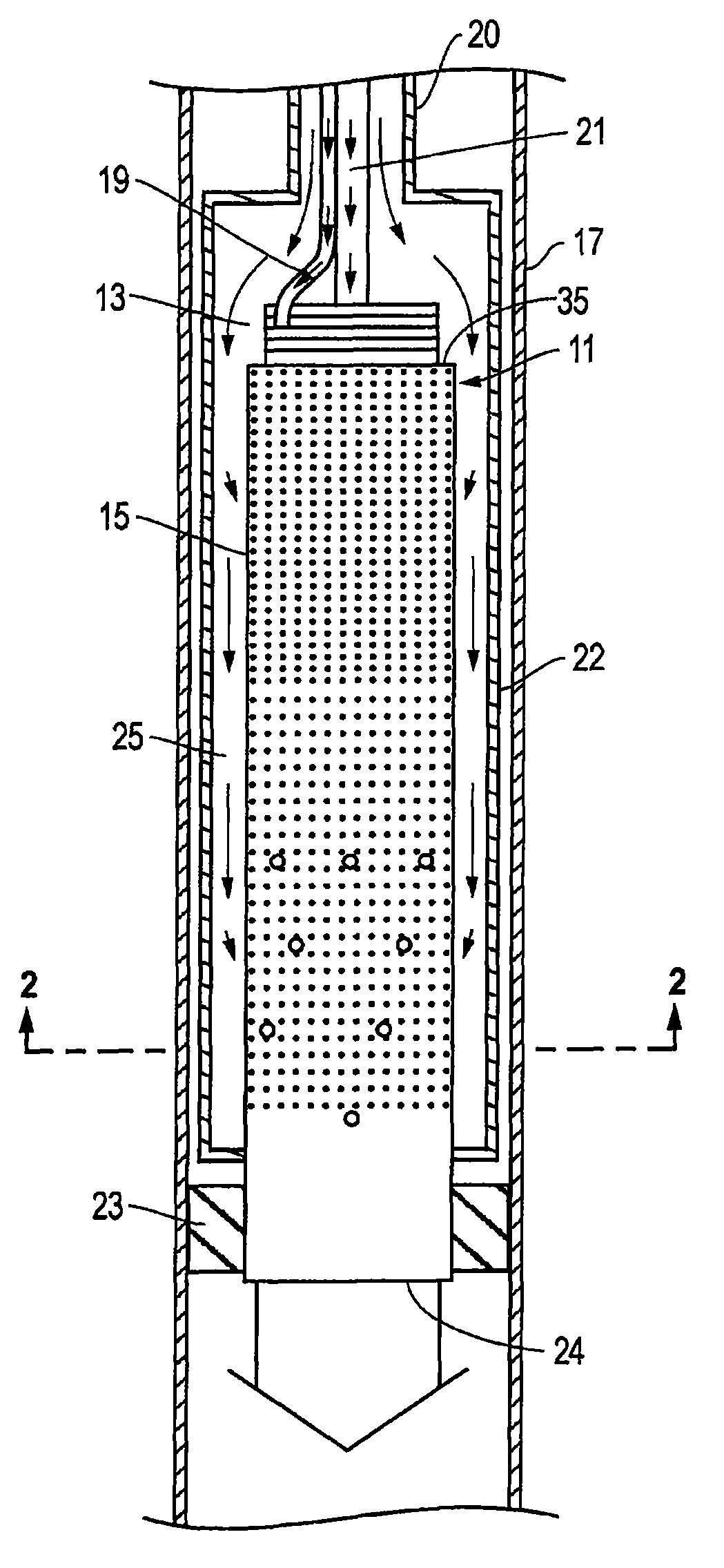
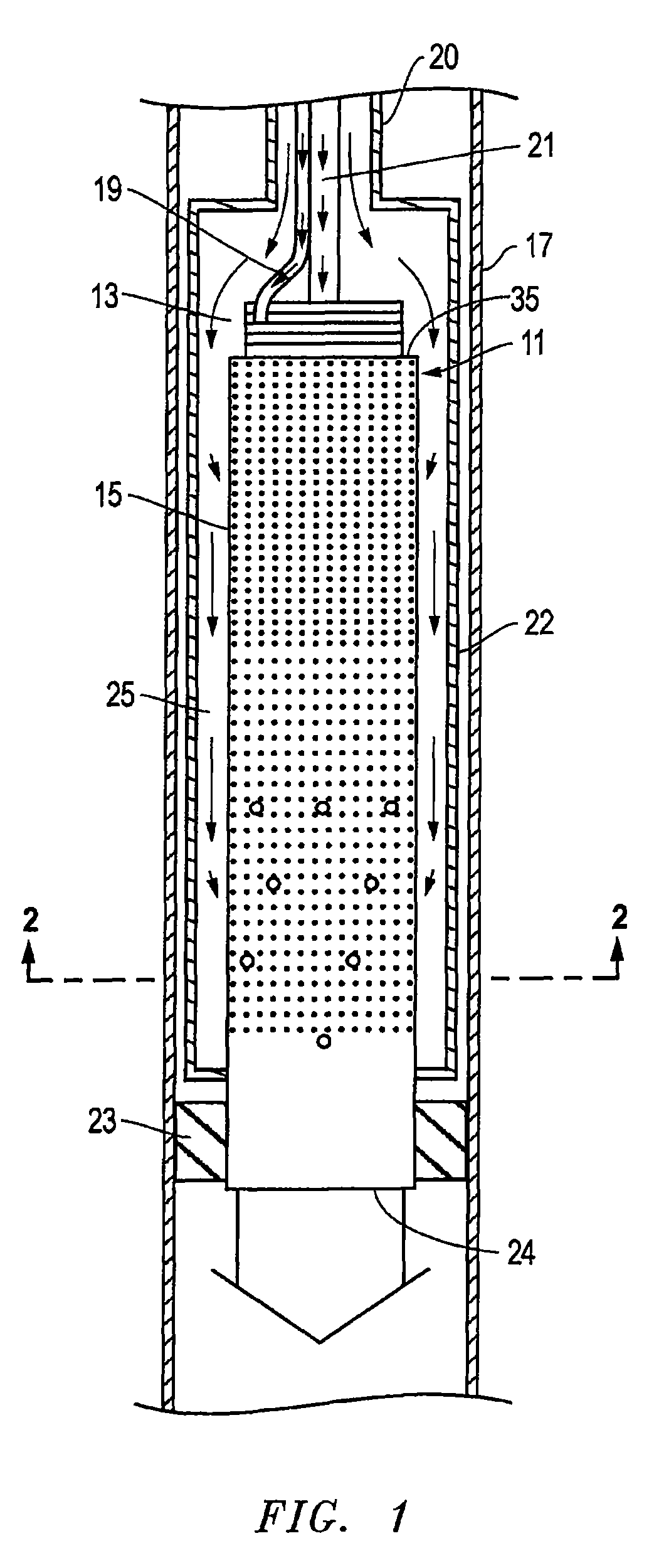
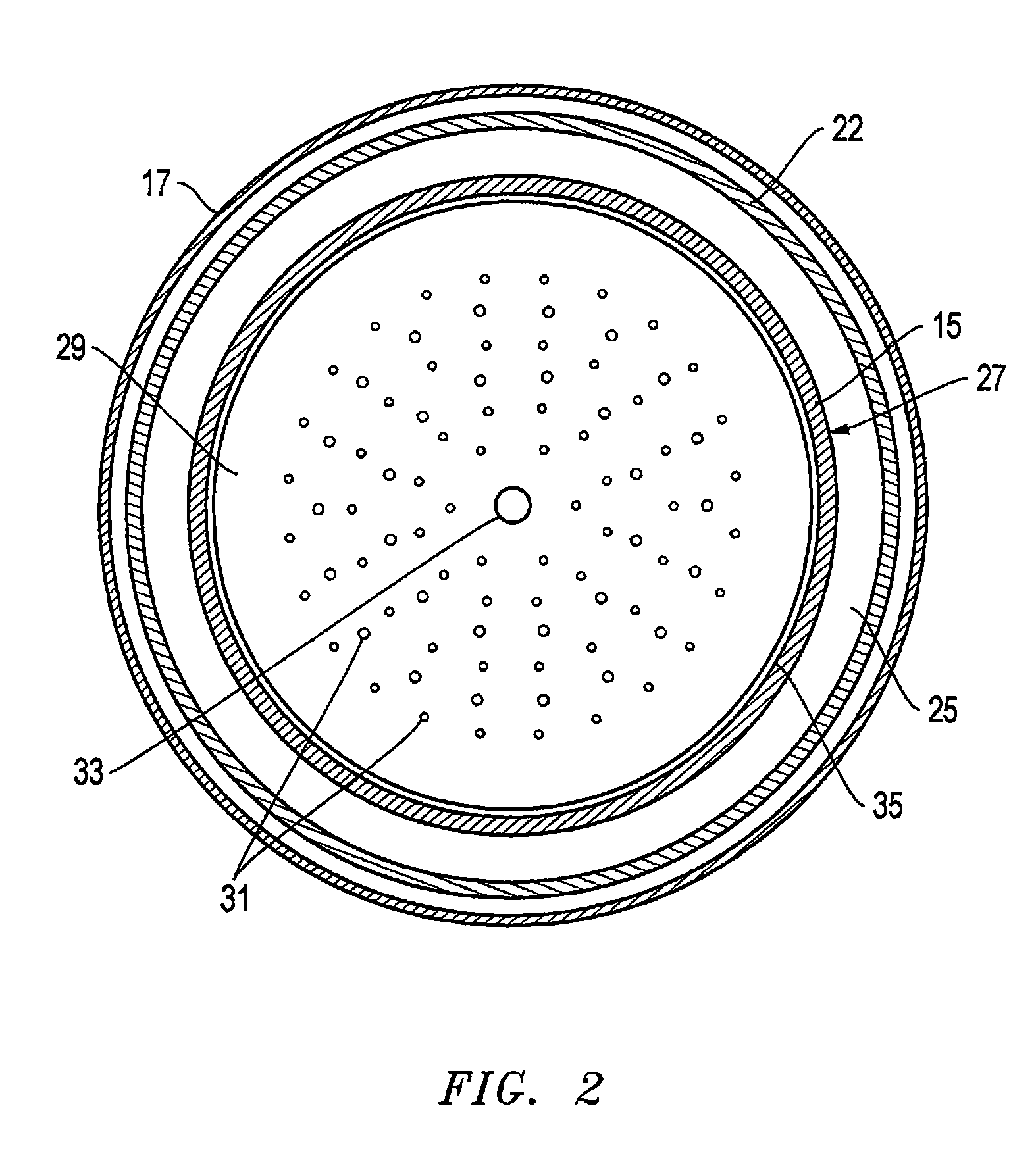
[0028]FIG. 1 depicts a downhole burner 11 positioned in a well according to an embodiment of the present invention. The well may comprise various wellbore configurations including, for example, vertical, horizontal, SAGD, or various combinations thereof. One skilled in the art will recognize that the burner also functions as a heater for heating the fluids entering the formation. A casing 17 and a packer 23 are shown in cross-section taken along the longitudinal axis of casing 17. Downhole burner 11 includes an injector 13 and a cooling liner...


PUM


Abstract

A downhole burner for a steam generator includes an injector and a cooling liner. Steam enters the burner through holes in the cooling liner. Combustion occurring within the cooling liner heats the steam and increases its quality and may superheat it. The heated, high-quality steam and combustion products exit the burner and enter an oil-bearing formation to upgrade and improve the mobility of heavy crude oils held in the formation. The injector includes a face plate, a cover plate, an oxidizer distribution manifold plate, and a fuel distribution manifold plate. The cooling liner has an effusion cooling section and effusion cooling and jet mixing section. The effusion cooling section includes effusion holes for injecting steam along the cooling liner surface to protect the liner. The effusion cooling and jet mixing section has both effusion holes and mixing holes for injecting steam further toward central portions of the burner.

Description

[0001]This non-provisional patent application claims priority to and the benefit of U.S. Provisional Patent App. Nos. 60 / 850,181, filed Oct. 9, 2006; 60 / 857,073, filed Nov. 6, 2006; and 60 / 885,442, filed Jan. 18, 2007.BACKGROUND OF THE INVENTION[0002]1. Technical Field[0003]The present invention relates in general to steam generators used downhole in wells and, in particular, to an improved system, method, and apparatus for a burner for a downhole steam generator.[0004]2. Description of the Related Art[0005]There are extensive viscous hydrocarbon reservoirs throughout the world. These reservoirs contain a very viscous hydrocarbon, often called “tar,”“heavy oil,” or “ultra heavy oil,” which typically has viscosities in the range from 3,000 to 1,000,000 centipoise when measured at 100 degrees F. The high viscosity males it difficult and expensive to recover the hydrocarbon. Strip mining is employed for shallow tar sands. For deeper reservoirs, heating the heavy oil in situ to lower th...

Claims


Application Information

Patent Timeline
Patent Type & Authority Patents(United States)
IPC IPC(8): E21B36/00E21B43/24
CPCE21B43/164E21B43/243E21B43/24
Inventor KLASSEN, MICHAELGOKULAKRISHNAN, PONNUTHURAIFULLER, CASEYHAMER, ANDREWWARE, CHARLES H.LANGDON, JOHN E.
Owner WORLD ENERGY SYST
Learn More