
Robust sensor correlation analysis for machine condition monitoring

a sensor correlation and machine condition technology, applied in the field of machine condition monitoring, can solve the problems of inability to directly achieve, difficult to obtain accurate physical models, and inability to accurately identify faults, etc., and achieve the effect of obtaining the desired clustering results

Inactive Publication Date: 2010-08-03
SIEMENS CORP
View PDF5 Cites 12 Cited by
  • Summary
  • Abstract
  • Description
  • Claims
  • Application Information

AI Technical Summary

Benefits of technology

[0014]Additionally, hierarchical clustering is applied to intuitively reveal the group information among sensors. By specifying a similarity threshold, the user can easily obtain desired clustering results.

Problems solved by technology

Violation of those physical relationships could indicate faults.
However, accurate physical models are often difficult to acquire.
In addition, the classical k-means clustering technique requires the calculation of the mean of each cluster, which is not directly possible using the correlation-coefficient based measure.

Method used


Image

  • Robust sensor correlation analysis for machine condition monitoring
  • Robust sensor correlation analysis for machine condition monitoring
  • Robust sensor correlation analysis for machine condition monitoring

Examples


Embodiment Construction

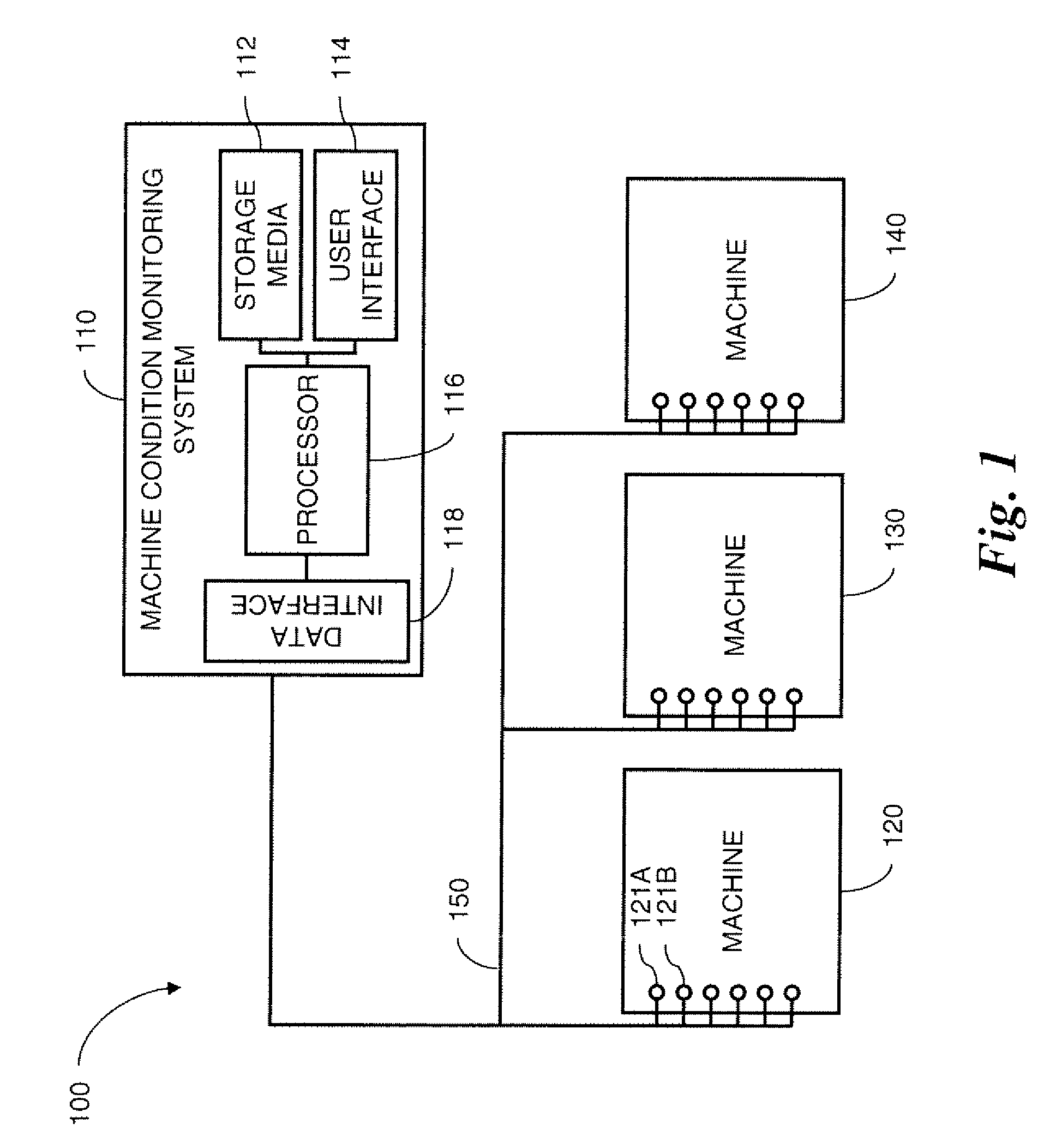
[0032]A system 110 for monitoring conditions of machines 120, 130, 140 according to one embodiment of the invention is shown in FIG. 1. The system includes a plurality of machine sensors such as the sensors 121A, 121B connected to machine 120. The sensors may, for example, be accelerometers, temperature sensors, flow sensors, position sensors, rate sensors, chemical sensors or any sensor that measures a condition of a machine or process. The sensors measure conditions chosen because they are related in predictable ways that reflect the presence or absence of normal operating conditions in an installation 100.

[0033]The sensors 121A, 121B are connected through a data network 150 to a data interface 118 in a machine condition monitoring system 110. A processor 116 receives the sensor data from the data interface 118 and performs the monitoring methods of the invention. The processor is connected to storage media 112 for storing computer-readable instructions that, when executed, perfor...


PUM


Abstract

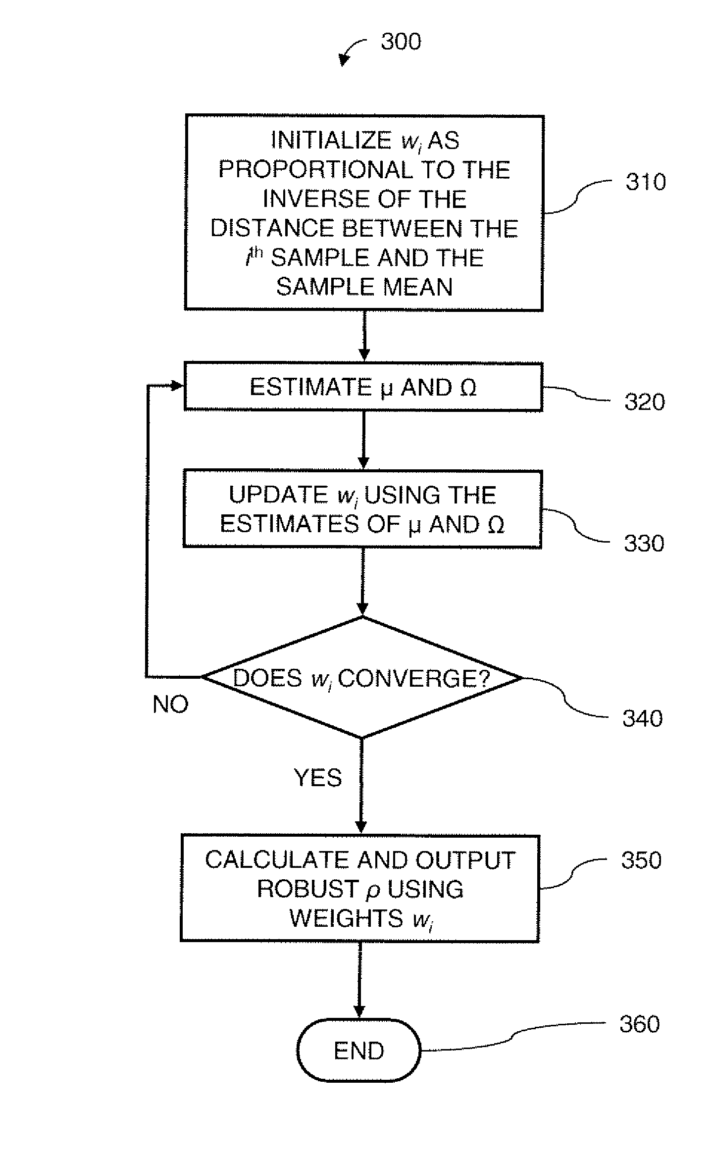
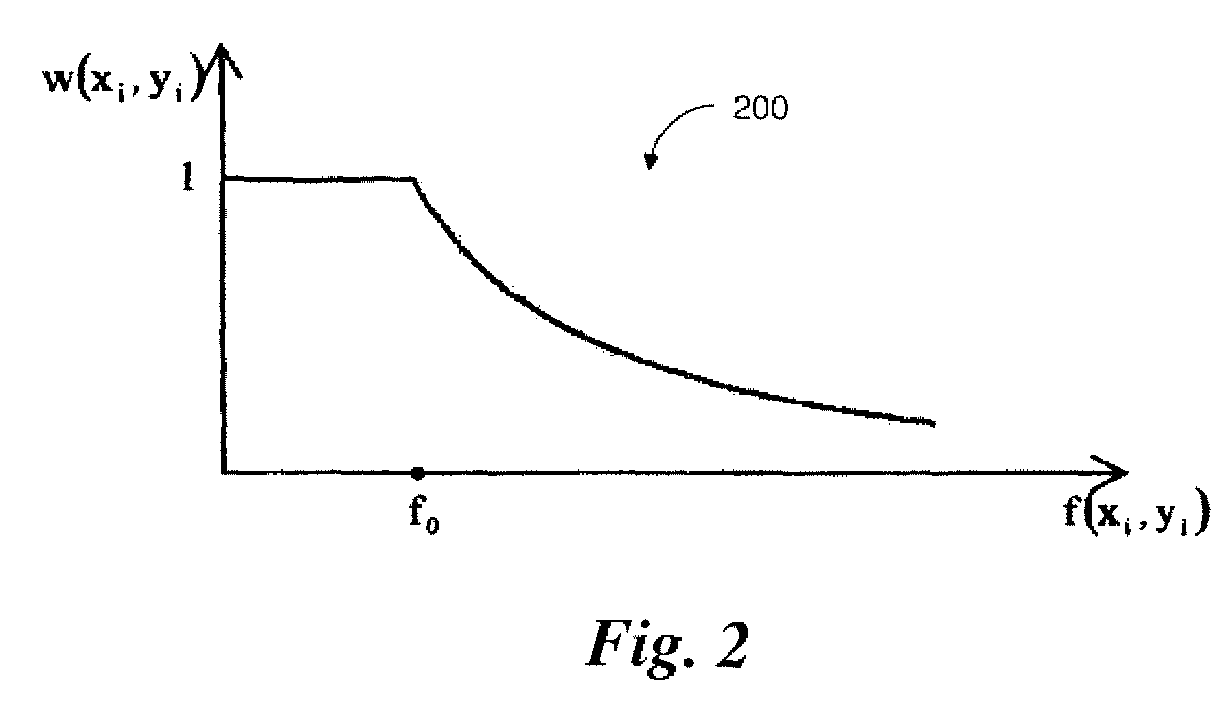
A method for monitoring machine conditions is based on machine learning through the use of a statistical model. A correlation coefficient is calculated using weights assigned to each sample that indicate the likelihood that that sample is an outlier. The resulting correlation coefficient is more robust against outliers. The calculation of the weight is based on the Mahalanobis distance from the sample to the sample mean. Additionally, hierarchical clustering is applied to intuitively reveal group information among sensors. By specifying a similarity threshold, the user can easily obtain desired clustering results.

Description

CROSS REFERENCE TO RELATED APPLICATIONS[0001]This application claims the benefit of U.S. Provisional Application Ser. No. 60 / 741,298 entitled “Robust Sensor Correlation Analysis for Machine Condition Monitoring,” filed on Dec. 1, 2005, the contents of which are hereby incorporated by reference in their entirety.FIELD OF THE INVENTION[0002]The present invention relates generally to the field of machine condition monitoring, and more particularly, to techniques and systems for the statistical modeling of relationships among machine sensors from historical data.BACKGROUND OF THE INVENTION[0003]Many manufacturing and service equipment installations today include, in addition to systems for controlling machines and processes, systems for machine condition monitoring. Machine condition monitoring systems include an array of sensors installed on the equipment, a communications network linking those sensors, and a processor connected to the network for receiving signals from the sensors and...

Claims


Application Information

Patent Timeline
Patent Type & Authority Patents(United States)
IPC IPC(8): G06F17/18
CPCG05B19/4065G05B23/024G05B2219/37508
Inventor YUAN, CHAOBALDERER, CHRISTIANHUANG, TZU-KUONEUBAUER, CLAUS
Owner SIEMENS CORP
Learn More