
Freight car event recorder

a technology for event recording and freight cars, applied in the field of system for conveying the operational condition of a railcar brake system, can solve the problems of increased wear on wheels and brake shoes, loss of efficiency, and excessive fuel consumption

Active Publication Date: 2010-08-03
WABTEC HLDG CORP
View PDF19 Cites 14 Cited by
  • Summary
  • Abstract
  • Description
  • Claims
  • Application Information

AI Technical Summary

Benefits of technology

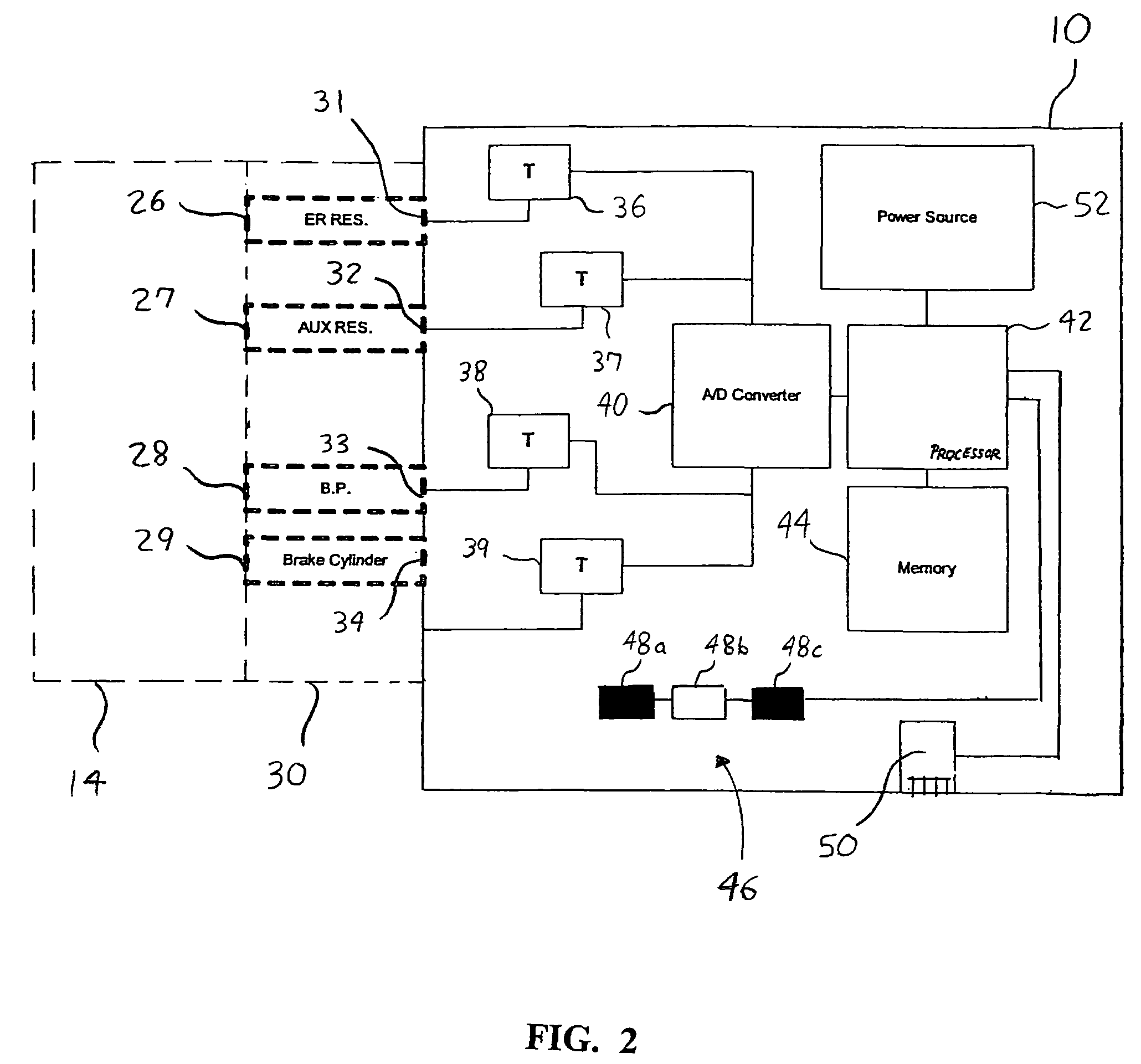
"The present invention is a device that allows for the visual recording of the operational condition of a brake system on a railcar. The device receives air from various components of the brake system and analyzes the pressure data to determine the overall performance of the brakes. The device is powered by a battery and includes a processor and indicator to visually convey the operational condition of the brakes. The device is designed to be easily installed on each railcar and does not require additional hardware. The technical effect of the invention is to provide a convenient and efficient way for maintenance personnel to monitor the performance of the brake system on their railcar."

Problems solved by technology

Improper functioning of braking equipment in a train consist may cause loss of efficiency, for example, excessive fuel consumption or increased wear on wheels and brake shoes.
However, the prior art testers provide a highly inefficient manner of obtaining the condition of the brake system.
With respect to the Rees and Vaughn patents, the testers are cumbersome in size and in connectivity.
The tedious act of connecting and reconnecting conduits to ports needs to be done for each railcar.
With respect to the Dougherty patent, the only manner in which the operational condition of the brake system may be viewed is by utilizing a hand-held wireless device, which may easily be lost.
The drawbacks of the invention disclosed in the Dougherty patent include, for example, the added expense of such wireless devices and the issue of availability of such wireless devices at various stations.
Furthermore, the prior art is only capable of performing testing while the train and its railcars are stationary.

Method used


Image

  • Freight car event recorder
  • Freight car event recorder
  • Freight car event recorder

Examples


Embodiment Construction

[0020]The present invention will now be described with reference to the accompanying figures. It is to be understood that the specific system illustrated in the attached figures and described in the following specification is simply an exemplary embodiment of the present invention.

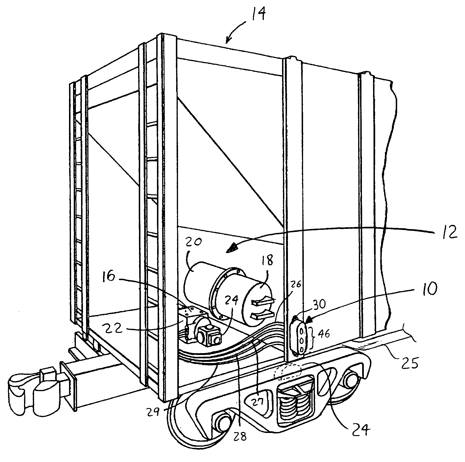
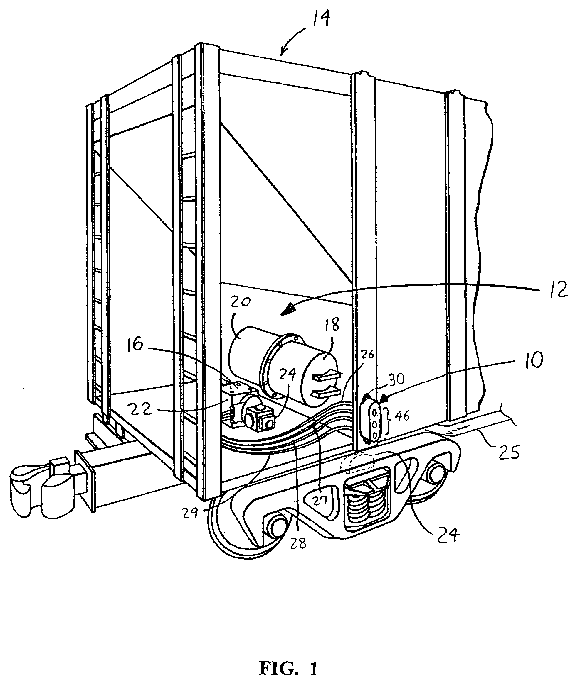
[0021]With reference to FIG. 1, an event recorder 10 for monitoring the performance and / or operational condition of a brake system 12 of a railcar 14 is disclosed. As known in the art, the typical railcar 14 may include a platform having a control valve device 16 with an auxiliary reservoir 18 and an emergency reservoir 20 mounted thereon. The control valve device 16 includes a pipe bracket portion 22 having a service portion 23 mounted on one side and an emergency portion (not shown) mounted on the opposite side. Another side of the pipe bracket portion 22 is provided with openings to which a brake cylinder 24, a brake pipe 25, the auxiliary reservoir 18 and the emergency reservoir 20 are connected via pi...


PUM


Abstract

A fixedly mountable event recorder for a railcar for monitoring performance of a brake system thereof includes (a) at least one port for receiving air from one or more brake system components; (b) at least one sensor for determining a pressure of the air received from the one or more brake system components; (c) a processor operative for analyzing the determined pressure to determine an operational condition of the brake system; and (d) an indicator configured to visually convey the operational condition of the brake system. The indicator includes a plurality of activatable visual indicia corresponding to a plurality of predefined operational condition status qualifiers associated with a corresponding plurality of predefined ranges of operational conditions. The predefined ranges of operational conditions are defined as a function of expected pressures associated with the respective one or more brake system components during corresponding operational conditions thereof.

Description

BACKGROUND OF THE INVENTION[0001]1. Field of the Invention[0002]The present invention relates generally to a system for conveying the operational condition of a railcar brake system.[0003]2. Description of Related Art[0004]A train consist typically includes a lead locomotive and one or more remote locomotives and railcars, comprehensively referred to as rolling stock. Each piece of rolling stock has braking equipment including, among other components, a section of brake pipe, a control valve, a brake cylinder, an emergency reservoir and an auxiliary reservoir. The brake pipe sections are connected forming a brake pipe that extends the length of the consist. The control valve directs pressurized air into and out of the brake cylinder as a result of changes in the level of brake pipe pressure. To apply train brakes, the brake pipe pressure decreases at a specified rate, which determines the percentage (e.g., amount of pressure) of brake applied.[0005]Proper functioning of the braking ...

Claims


Application Information

Patent Timeline
Patent Type & Authority Patents(United States)
IPC IPC(8): G06F7/00
CPCB60T17/228
Inventor GAUGHAN, EDWARD W.DIMSA, ROBERT D.SICH, GARY M.VELTRI, MICHAEL J.
Owner WABTEC HLDG CORP
Learn More