
Method for warming-up a steam turbine

a steam turbine and steam heating technology, applied in the direction of machines/engines, instruments, mechanical means, etc., can solve the problems of increasing unsaturated steam, high material stress, and high cost of achieving high steam quality

Inactive Publication Date: 2010-08-03
SIEMENS ENERGY GLOBAL GMBH & CO KG
View PDF12 Cites 12 Cited by
  • Summary
  • Abstract
  • Description
  • Claims
  • Application Information

AI Technical Summary

Benefits of technology

The invention is about a method for warming up a steam turbine faster by using high-quality steam. The method involves increasing the back-pressure of the high-pressure turbine section, allowing the steam to flow through it and improve heat transfer. This allows the turbine to warm up faster and at higher saturation temperatures, resulting in increased efficiency and reduced corrosion stress. The method can be used even when the steam quality is not very good, and it is particularly useful for high-pressure turbine sections. Overall, the method allows for a faster and more effective prewarming of the steam turbine.

Problems solved by technology

As a result of the exposure to superheat steam admission, high material stresses, due to the thermal expansion stresses which occur, are regularly brought about during starting from a cold machine state.
The cost for achieving a high steam quality is relatively high.
If saturated steam is separated from a solid or condensate and is heated at constant pressure, then the steam becomes increasingly unsaturated.
The subdivision into high-pressure, intermediate-pressure, and low-pressure turbine sections is not uniformly applied within the specialist field.
Therefore, the steam parameters, such as temperature and pressure, cannot be used as a single differentiating criterion between a high-pressure, intermediate-pressure and low-pressure turbine section.

Method used


Image

  • Method for warming-up a steam turbine
  • Method for warming-up a steam turbine

Examples


Embodiment Construction

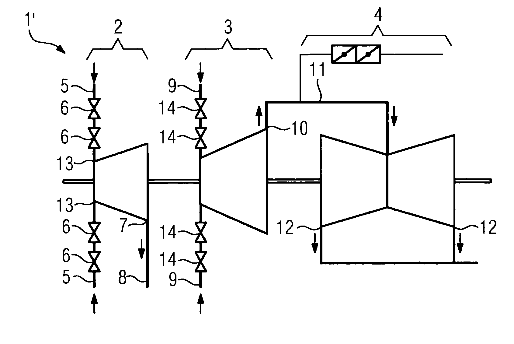
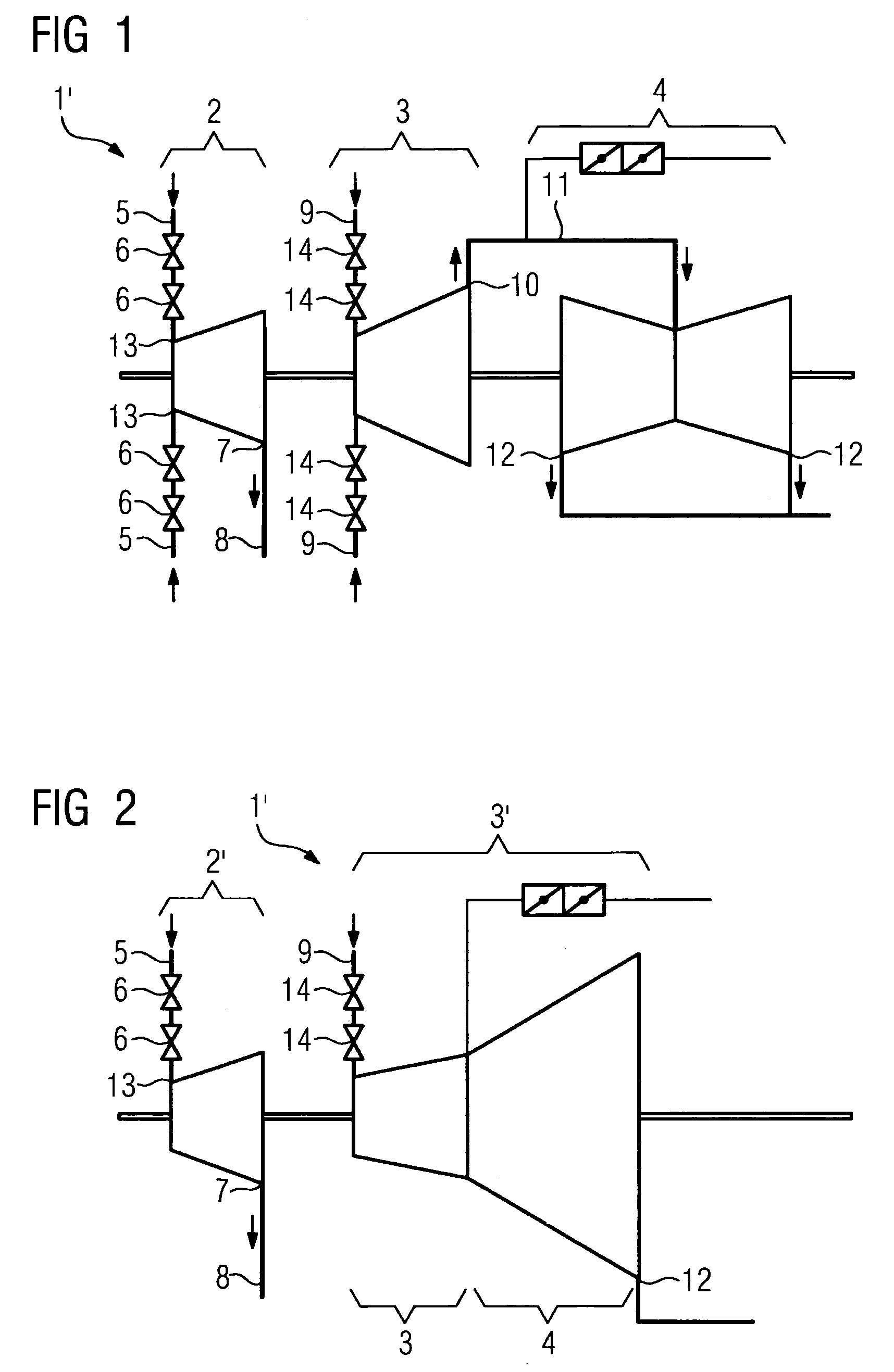
[0036]In FIG. 1, a schematic representation of a steam turbine 1, which comprises a high-pressure turbine section 2, an intermediate-pressure turbine section 3, and a double-flow low-pressure turbine section 4, is shown. The high-pressure turbine section 2 comprises at least two live steam lines 5, wherein valves 6 are arranged in a live steam line 5. The valves 6 are formed for controlling the throughflow of steam which flows through the live steam line 5, The live steam is produced in a steam generator or boiler which is not shown in more detail. Via the live steam line 5 and the valves 6, the steam which is produced in the steam generator reaches the high-pressure turbine section 2, is expanded there, and then issues from the high-pressure turbine section 2 at the outlet 7. Via an exhaust steam line 8, the expanded steam reaches a reheater, which is not shown in more detail, and is heated there to a higher temperature, and is then fed via at least one intermediate-pressure inlet ...


PUM

PropertyMeasurementUnit
temperatureaaaaaaaaaa
pressureaaaaaaaaaa
temperatureaaaaaaaaaa

Abstract

The invention relates to a method for heating a steam turbine comprising a high-pressure turbine section and a medium-pressure turbine section and / or a low-pressure turbine section. Said method is characterized by the essential aspect that the high-pressure turbine section is impinged upon by steam having relatively great conductivity while the medium-pressure turbine section or the low-pressure turbine section remains closed during said impingement following a cold start. As soon as the conductivity drops below a certain value, the medium-pressure turbine section or the low-pressure turbine section is also impinged upon by steam.

Description

CROSS REFERENCE TO RELATED APPLICATIONS[0001]This application is the U.S. National Stage of International Application No. PCT / EP2006 / 066794, filed Oct. 12, 2005 and claims the benefit thereof. The International Application claims the benefits of European application No. 05022278.5 filed Oct. 12, 2005, both of the applications are incorporated by reference herein in their entirety.FIELD OF INVENTION[0002]The invention relates to a method for warming-up a steam turbine, wherein the steam turbine comprises a high-pressure turbine section and an intermediate-pressure and / or a low-pressure turbine section, wherein the high-pressure turbine section on the inlet side is fluidically connected via a live steam line to a steam generator, wherein a steam valve is arranged between the high-pressure turbine section and the intermediate-pressure turbine section, wherein the high-pressure turbine section, the live steam line and the steam generator are warmed-up in parallel.BACKGROUND OF THE INVEN...

Claims


Application Information

Patent Timeline
Patent Type & Authority Patents(United States)
IPC IPC(8): F01K13/02F01K13/00F01K7/34F01K23/06G01N27/12
CPCF01D25/10F01K7/18F01K7/20F01K7/22F01K7/24F01K13/02Y02E20/16
Inventor DIESTERBECK, HENRIGOBRECHT, EDWINPETERS, KARSTENQUINKERTZ, RAINER
Owner SIEMENS ENERGY GLOBAL GMBH & CO KG
Learn More