Cylinder valve spring compressor

a compressor and valve spring technology, applied in the field of manual operation can solve the problems of valve spring compressors, valve stem seals that lose effectiveness gradually, oil leakage into combustion chambers,

Inactive Publication Date: 2010-08-03
DUARTE ROMEO ANTONIO
View PDF8 Cites 8 Cited by
  • Summary
  • Abstract
  • Description
  • Claims
  • Application Information

AI Technical Summary

Benefits of technology

[0012]Another feature and advantage of the present invention is that all parts are rigid, and made of steel or other suitable material, thus making the tool durable and safe.
[0013]Another feature and advantage of the present invention is that the cylindrical body element of the valve spring compressor can move back and forward, and left to right when mounted on the transverse bar that is slidably disposed on the bracket for the purpose of clearing obstacles and allow the positioning of the tool over any valve.
[0014]Another feature and advantage of the present invention is that the cylindrical body element of the valve spring compressor is threaded at the external lower portion of the body to allow adjustments in the height of the tool.
[0015]Another feature and advantage of the present invention is that the handle can rotate with the cylindrical body element of the valve spring compressor tool for the purpose of clearing objects and to adjust the height of the compressing member.
[0016]Another feature and advantage of the present invention is that the pushrod slides up and down in the cylindrical body of the valve spring compressor and is returned to the rest position by a spring, the push rod providing a push action for attachment of the compressing member and also assist in adjusting the height of the compressing member.
[0017]Another feature and advantage of the present invention is that different sizes of the compressing member are made to provide a proper push action on top of the valve spring retainers.

Problems solved by technology

Over time, valve stem seals lose effectiveness gradually and oil leaks into the combustion chambers, this oil gets burned during the power stroke producing hydrocarbons that exit from the tail pipe.
In one method and still the most preferred, the cylinder is pressurized with air in order to hold the valves, however, the disadvantage is the set up of the tool that permits the valve spring compressor to move from one valve spring to the other.
It is also a time consuming method, and another disadvantage is the problem of firmly holding the tools in place that sometimes can result in injuries to the technician.
The disadvantage is that this tool only fits in few type cylinder head design.

Method used


Image

  • Cylinder valve spring compressor
  • Cylinder valve spring compressor
  • Cylinder valve spring compressor

Examples


Embodiment Construction

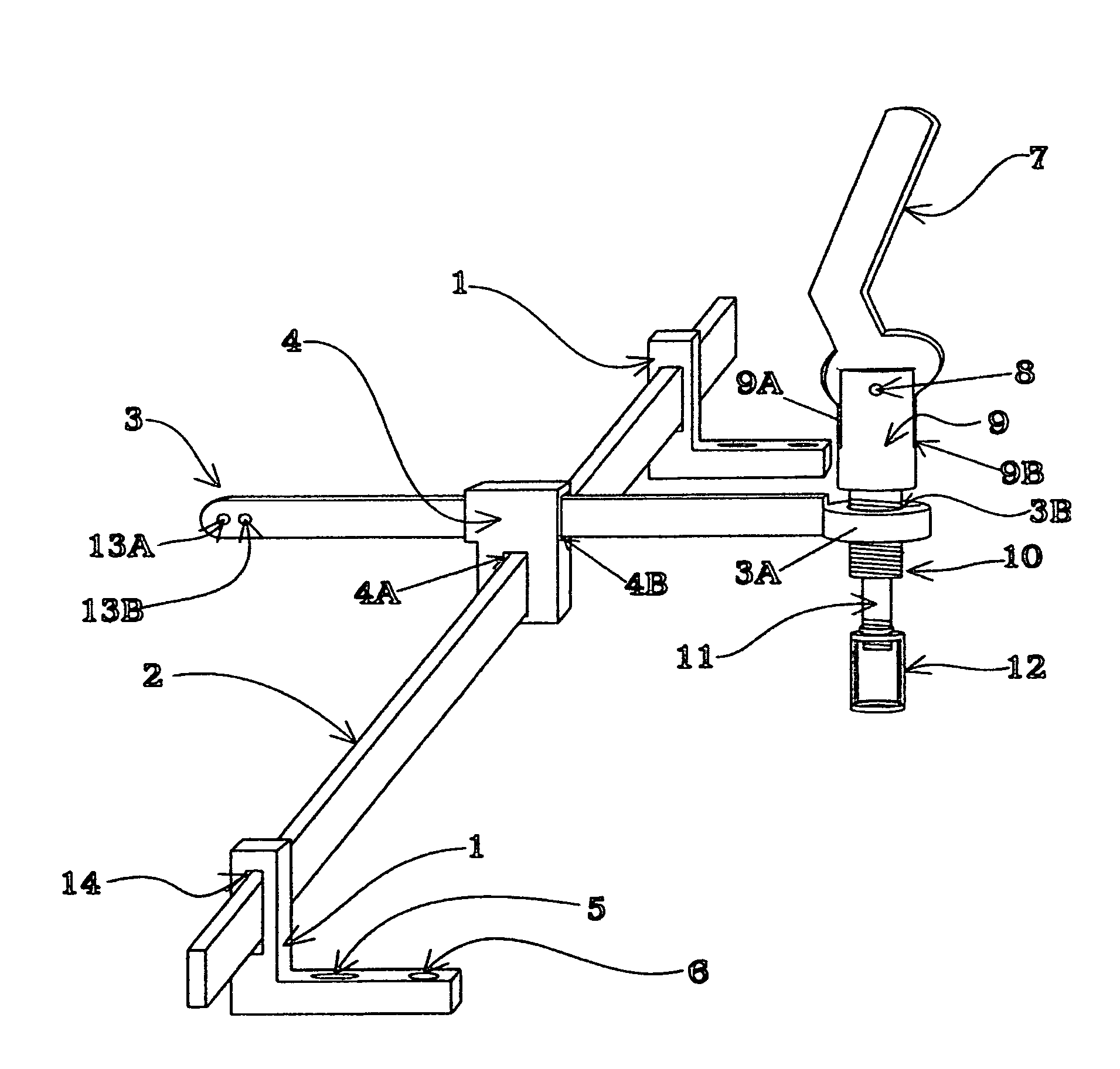
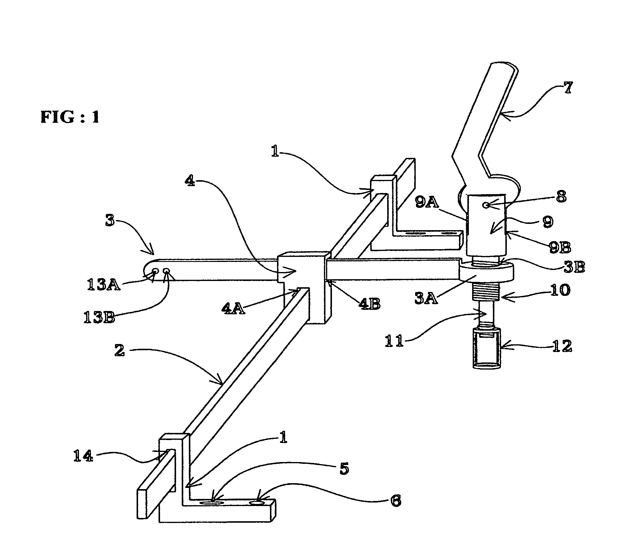
[0028]In the following discussion, the dimensions of the components are provided for purposes of example only, and are not limited thereto. FIG. 1 illustrates the complete assembly of the valve spring compressor when mounted on two brackets or stands 1 that are identical in shape and size. The bottom section or base of bracket 1 is 80 mm long and 20 mm high, the upper section is 52 mm high and 20 mm wide, and an elongated aperture 14 is located at 22 mm from the bottom edge of the base of bracket 1 and 5 mm from the top edge at the center of the upper portion of bracket 1. The thickness of bracket 1 is 17 mm.

[0029]Two apertures are disposed on the top of the bottom portion or base of bracket 1 that are used to secure bracket 1 onto the cylinder head while using two bolts. One aperture 6 is round and is of 7 mm in diameter and is located at 4 mm from right to left of base of bracket 1 as seen in FIG. 1.

[0030]The second aperture 5 on top of bottom portion of bracket 1 is an elongated ...


PUM

PropertyMeasurementUnit
thicknessaaaaaaaaaa
diameteraaaaaaaaaa
diameteraaaaaaaaaa

Abstract

A valve spring compressor apparatus and method for compressing cylinder valve springs for the removal and installation of their locks or keepers and for replacement of valve stem seals or broken springs on an internal combustion engine, while the cylinder head is mounted on the engine or supported on a work bench. A compressor tool adjustably mounted on a support assembly temporarily secured over the cylinder head has a pivoting hand lever and spring biased push rod which, when manually depressed, moves a compressing member at the bottom of the push rod downward to engage and depress the valve spring and its retainer to gain access and removal of the lock or keeper though openings in the compressor tool.

Description

CROSS REFERENCE TO RELATED APPLICATION[0001]This non-provisional application claims priority of U.S. provisional application Ser. No. 60 / 964,840, filed on Aug. 15, 2007.FIELD OF THE INVENTION[0002]The present invention relates generally to manually operated valve spring compressing tools used in the removal and replacement of valve springs and valve stem seals on overhead camshaft cylinder heads, and more particularly to a valve spring compressor apparatus and method wherein a compressor tool adjustably mounted on a support assembly temporarily secured over the cylinder head has a pivoting hand lever and spring biased push rod which, when manually depressed, moves a compressing member at the bottom of the push rod downward to engage and depress the valve spring and its retainer to gain access and removal of the lock or keeper though openings in the compressor tool.BACKGROUND OF THE INVENTION[0003]Over time, valve stem seals lose effectiveness gradually and oil leaks into the combust...

Claims


Application Information

Patent Timeline
Patent Type & Authority Patents(United States)
IPC IPC(8): B23P19/04B23P17/00
CPCB25B27/24B25B27/26Y10T29/53561Y10T29/49314Y10T29/53843Y10T29/53961
Inventor DUARTE, ROMEO ANTONIO
Owner DUARTE ROMEO ANTONIO
Why Eureka
Try Eureka