
Image formation apparatus

a technology of image formation and apparatus, which is applied in the direction of electrographic process, instruments, transportation and packaging, etc., can solve the problems of large rotary load of cams, inability to set sheets, and large vigor of lift plates, so as to achieve excellent safety and operability, and the space for a fixed guide can be made smaller.

Inactive Publication Date: 2010-07-27
FUJIFILM BUSINESS INNOVATION CORP
View PDF12 Cites 0 Cited by
  • Summary
  • Abstract
  • Description
  • Claims
  • Application Information

AI Technical Summary

Benefits of technology

The present invention provides an image formation apparatus with a compact and safe paper supply section. The apparatus includes a paper supply section that can be easily mounted and a feeding section that moves sheets of paper to the main body of the apparatus. A cam is connected to a baseplate, which pushes the paper towards the feeding section. An arm is connected to the baseplate and swings in response to the rotation of the cam. This design ensures that the baseplate stays in place when the paper supply section is removed, which improves safety and ease of use. Additionally, the arm can be swung after mounting the paper supply section to make space for a fixed guide smaller.

Problems solved by technology

However, when sheets are to be loaded, setting of the sheets is not possible unless the baseplate is moved away from the feeding mechanism.
However, with a paper supply unit as described above, it is necessary for the push-down cam to be pushed up by a rotary cam at times of paper supply, and there has been a problem in that a rotary load of the cams is large.
Therefore, if, during setting of the sheets, the push-down cam is removed from the lift plate for some reason, the lift plate will rise with great vigor and there is a danger of fingers being nipped or the like.
Furthermore, if the rotary cam is offset from a proper position thereof for some reason, the rotary cam and the push-down cam may collide during insertion of the paper supply unit.
Hence, since there is urging by the push-down cam, if the push-down cam has been specified so as to ride up on the rotary cam, resistance when the push-down cam rides up contributes to resistance to the insertion, and it may be more difficult to mount the paper supply unit at the apparatus.
However, in such a paper supply unit, since the guide is a fixed guide, it is inherently not possible to move up and down the baseplate after the mounting of the paper supply unit.
Furthermore, the fixed guide takes up length, so more space is required in the direction of insertion of the cassette.

Method used


Image

  • Image formation apparatus
  • Image formation apparatus
  • Image formation apparatus

Examples


first embodiment

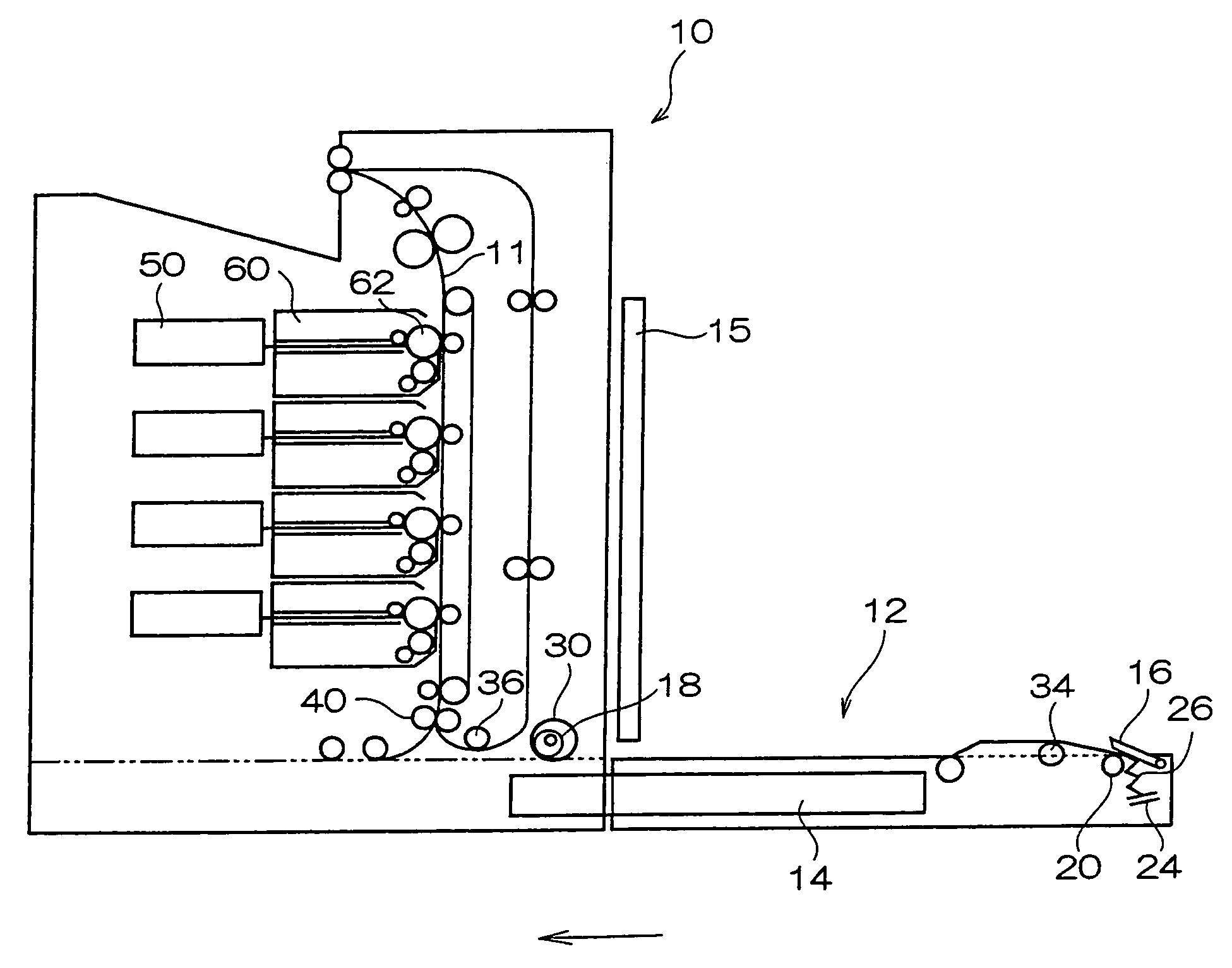
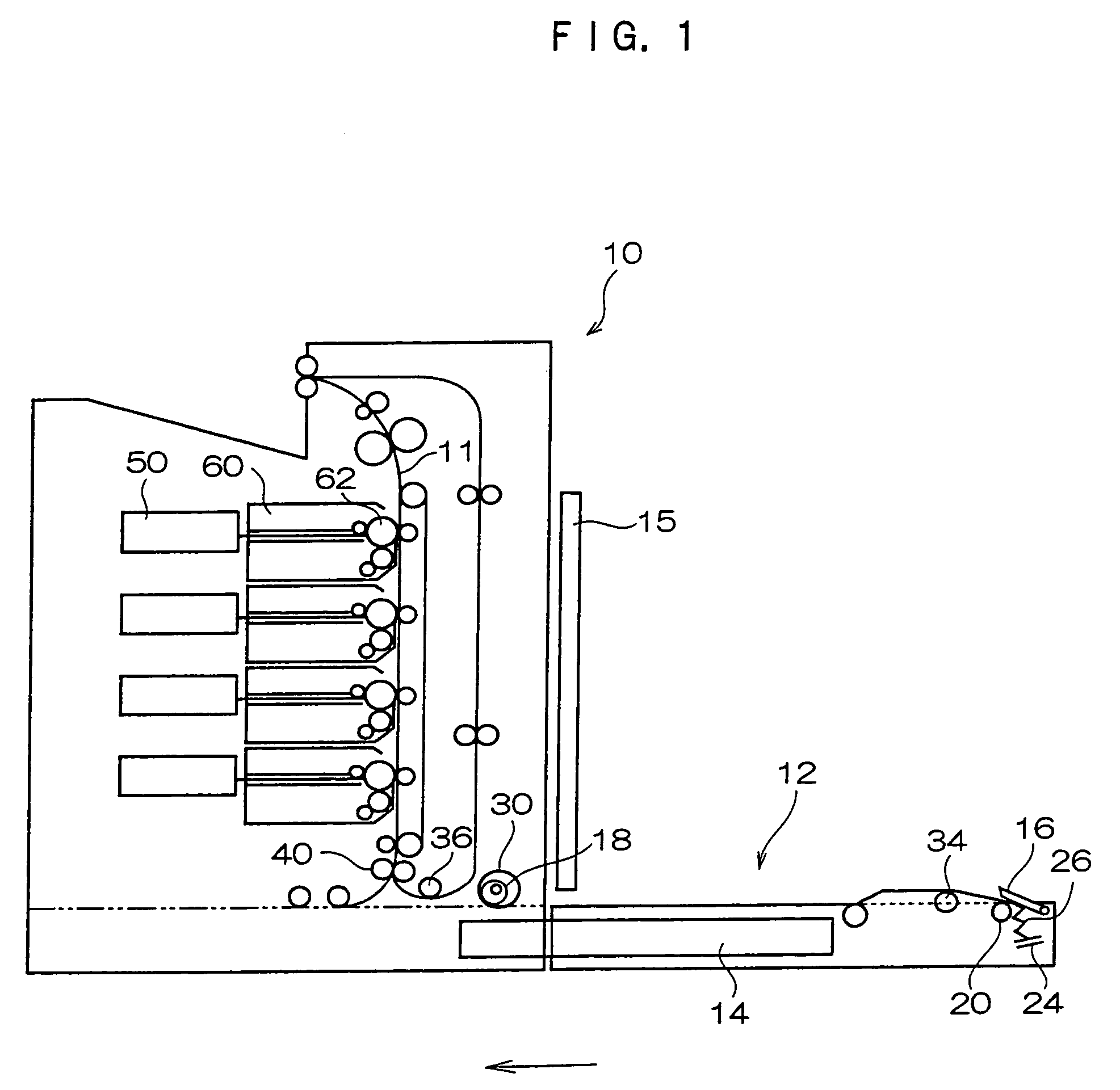
[0019]FIG. 1 shows structure of an image formation apparatus relating to the present invention.

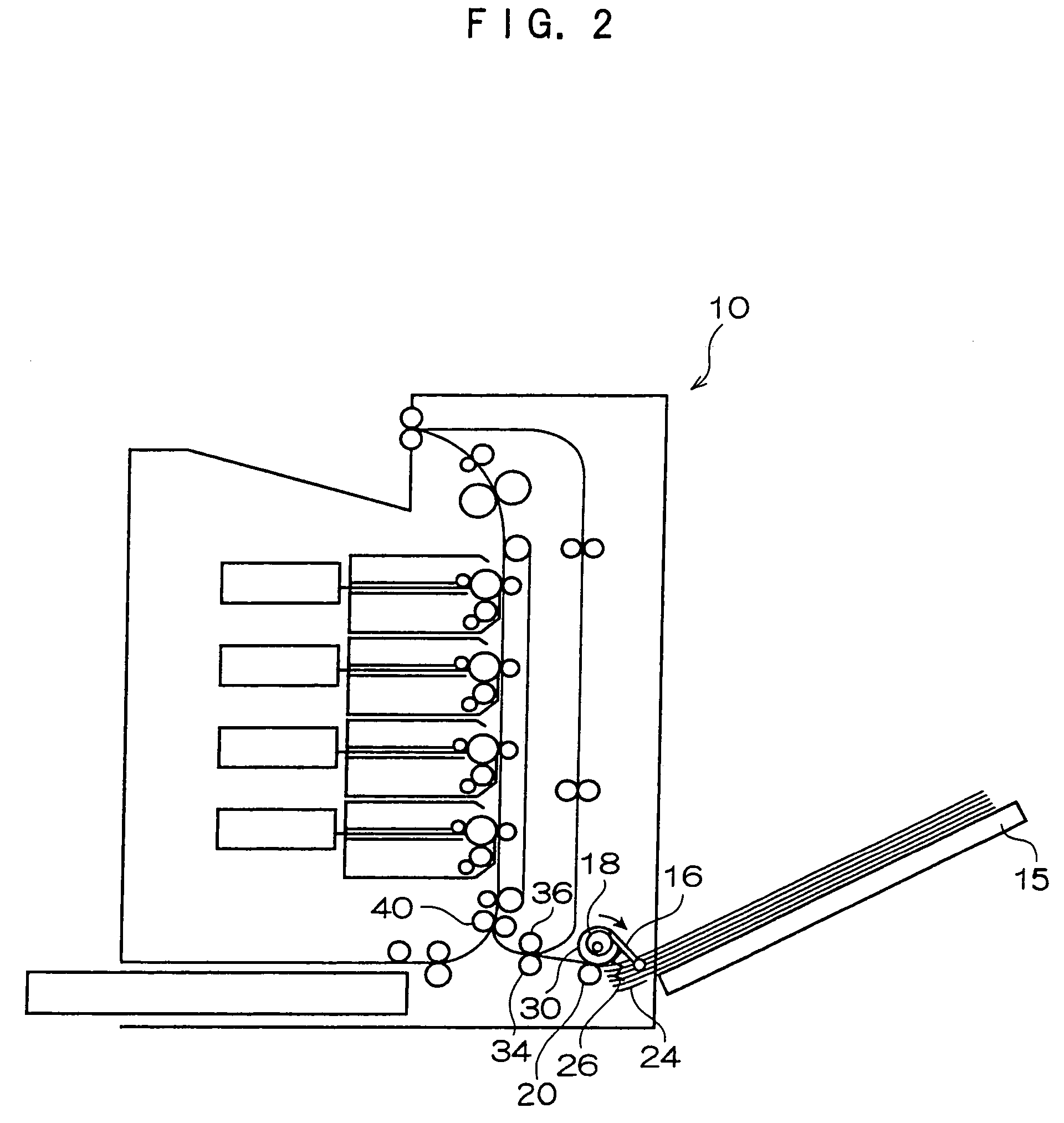
[0020]As shown in FIG. 1, an image formation apparatus 10 is an electrophotography-type image formation apparatus which implements image exposure onto a photosensitive body 62 with an ROS 50, develops a latent image formed on the photosensitive body 62 with toner in a developing unit 60, transfers the toner onto a sheet which is being conveyed along a conveyance path 11, and fixes the toner at a fixing unit to form an image.

[0021]A sheet accommodation section 14 is provided at a cassette 12, which is mounted at the image formation apparatus 10. Sheets on which image formation is to be performed are accommodated in the sheet accommodation section 14. The cassette 12 is installed in the apparatus main body as shown by the arrow in the drawing, the sheets in the sheet accommodation section 14 are conveyed into the apparatus main body one-by-one, in order from a top sheet, and image formation ...


PUM


Abstract

An image formation apparatus includes a paper supply section, a feeding section, a cam, a baseplate and an arm portion. The paper supply section is withdrawably mounted at a main body of the image formation apparatus. The feeding section is provided at the image formation apparatus main body and feeds a sheet. The cam is provided at the image formation apparatus main body and rotates in conjunction with the feeding section. The baseplate is provided at the paper supply section and is urgeable the sheet toward the feeding section. The arm portion is swingably provided at the paper supply section. When the paper supply section is installed at the image formation apparatus main body, the arm portion swings with rotation of the cam together with the feeding section and, via the resilient member, the arm portion urges the baseplate toward the feeding section.

Description

CROSS-REFERENCE TO RELATED APPLICATION[0001]This application claims priority under 35 USC 119 from Japanese Patent Application No. 2005-187414, the disclosure of which is incorporated by reference herein.BACKGROUND OF THE INVENTION[0002]1. Field of the Invention[0003]The present invention relates to an image formation apparatus.[0004]2. Description of the Related Art[0005]Ordinarily, at an image formation apparatus such as a printer or the like, sheets at which images are to be formed are accommodated in advance at a paper supply unit, such as a cassette, a magazine or the like, which is withdrawably mounted at an apparatus main body. The sheets are taken out one at a time by a feeding mechanism provided at the apparatus main body and are fed to an image formation section, and image formation is implemented. At such a time, in order for the sheets to be taken out by the feeding mechanism with conveyance characteristics being kept constant regardless of the number of sheets remaining...

Claims


Application Information

Patent Timeline
Patent Type & Authority Patents(United States)
IPC IPC(8): B65H3/24
CPCB65H5/062B65H2403/512B65H2404/1112B41J13/103G03G15/00G03G15/6508G03G2215/00556
Inventor KUROKAWA, YASUHIRO
Owner FUJIFILM BUSINESS INNOVATION CORP
Learn More