Slide rail assembly and slide rail assembly pair

a technology of slide rail and assembly pair, which is applied in the direction of furniture parts, machine supports, building scaffolds, etc., can solve the problems of sliding of the ups relative to the cabinet, high cost, complex structure, etc., and achieves simple structure and good operability and security.

Active Publication Date: 2016-05-12
EATON INTELLIGENT POWER LTD
View PDF5 Cites 12 Cited by
  • Summary
  • Abstract
  • Description
  • Claims
  • Application Information

AI Technical Summary

Benefits of technology

[0005]The technical problem to be addressed by the present invention lies in providing a slide rail assembly and a slide rail assembly pair which not only have good operability and security during use, but also have a simple structure.
[0006]In one aspect, there is provided a slide rail assembly, comprising: a first slide rail including a first, elongated web plate which has a front surface facing toward the carried item and a back surface facing away from the carried item in use; a second slide rail nested within the first slide rail and being movable relative to the first slide rail in length direction. The upper edge of the first web plate is provided with a first, L-shaped upper folded panel extending at an angle of 90 degrees with regard to the back surface of the first web plate, the lower edge of the first web plate is provided with a horizontal supporting panel used for supporting the item and bended at an angle of 90 degrees with regard to the front surface of the first web plate, and the first web plate is further provided with at least one first, L-shaped lower folded panel opposite to the first upper folded panel and extending at an angle of 90 degrees with regard to the back surface of the first web plate, with the first upper folded panel and said at least one first lower folded panel collectively constituting a slide chute for supporting and guiding the second slide rail sliding therein. Each of the first slide rail and the second slide rail of the slide rail assembly is punched out from an integral sheet, and thus has a simple structure and a high strength of structure, and is easy to manufacture, so that the production efficiency will be greatly improved and the cost will be reduced.
[0008]Preferably, the second slide rail includes a second, elongated web plate, and the front surface of the second web plate is provided with a recess extending in the length direction of the second web plate. Optionally, the first web plate is also provided with a first protruding panel extending toward its back surface into the recess, the second slide rail has a first end surface and a second end surface, and the recess comprises a third end surface and a fourth end surface which are separated from the first end surface and the second end surface at given distances respectively, with the third end surface and the fourth end surface constituting stop means for stopping the movement of the first protruding panel in the length direction. The arrangement of the recess not only effectively increases the strength of the slide rail, but also tactfully forms a stopping and guiding means for the relative sliding between the first slide rail and the second slide rail.

Problems solved by technology

In use, pushing a UPS will lead to the sliding of the inner rail fixed on the UPS relative to the outer rail under the guidance of the outer rail, thus causing the sliding of the UPS relative to the cabinet.
Accordingly, the existing slide due to their simple structures could be neither satisfied for the requirements of smooth operation nor safety during use, or due to various additional mechanisms on the slide rail assembly for smooth and safe operation, leads to complex structures and high costs.

Method used


Image

  • Slide rail assembly and slide rail assembly pair
  • Slide rail assembly and slide rail assembly pair
  • Slide rail assembly and slide rail assembly pair

Examples


Embodiment Construction

[0071]The specific embodiments and examples according to the present invention will be described in detail as follows, in order to assist the skilled in the art in understanding the abovementioned aspects and features as well as other aspects and features of the invention more clearly. It is understood that the skilled in the art is able to make various modifications and substitutions to the specific embodiments and examples described herein without departing the scope of the invention, which modifications and substitutions all fall into the protection scope of the present invention.

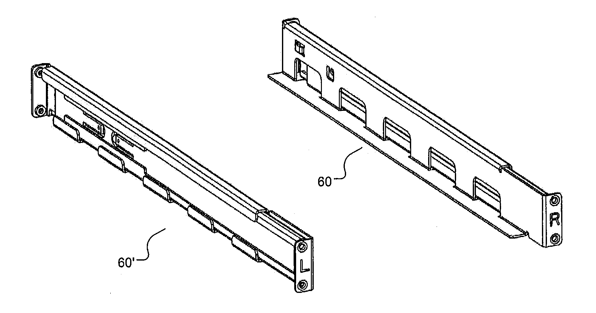
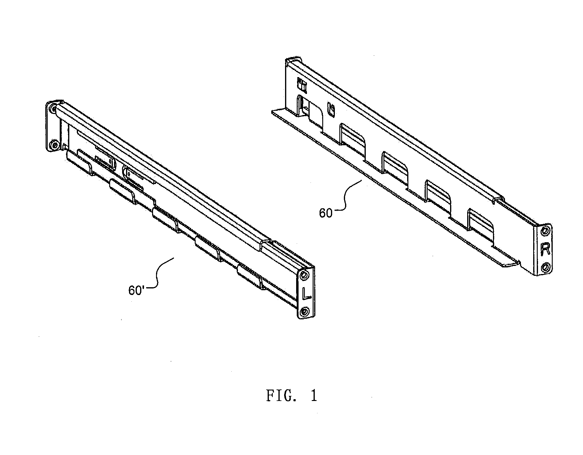
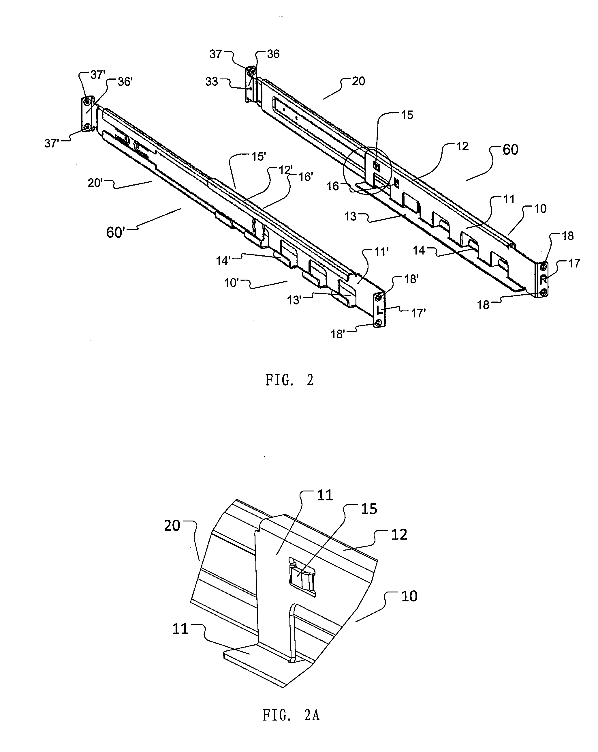
[0072]FIGS. 1, 2 and 3 illustrates an embodiment of slide rail assembly pair according to the present invention which can be used to installing a UPS onto a cabinet. The slide rail assembly pair comprises a first slide rail assembly 60′ and a second slide rail assembly 60. Each slide rail assembly has three-section slide rails, that is, the first slide rail assembly 60′ and the second slide rail assembly...


PUM


Abstract

A slide rail assembly comprising: a first slide rail (10, 10′) comprising a first, elongated web plate (11, 11′), a front surface facing toward a carried item (80) in use and a back surface facing away from the carried item in use; a second slide rail (20, 20′) nested within the first slide rail and being movable relative to the first slide rail in length direction. The upper edge of the first web plate is provided with a first, L-shaped upper folded panel (12, 12′) extending at an angle of 90 degrees with regard to the back surface of the first web plate, the lower edge thereof is provided with a horizontal supporting panel (13, 13′) for supporting the item which is bended at an angle of 90 degrees with regard to the front surface of the first web plate, and the first web plate is also provided with at least one first, L-shaped lower folded panel (14, 14′) opposite to the first upper folded panel and extending at an angle of 90 degrees with regard to the back surface of the first web plate, with the first upper folded panel and the at least one first lower folded panel collectively constituting a slide chute for supporting and guiding the second slide rail sliding therein.

Description

TECHNICAL FIELD[0001]The present invention relates to a slide rail assembly and a slide rail assembly pair and, in particular, to a slide rail assembly and slide rail assembly pair for carrying UPS (uninterruptible power supply).BACKGROUND[0002]Slide rail is a mechanic device that is widely employed to carry an item, such as a drawer, a server or a UPS, to be slid relative to other structures. In the simplest way, the slide rail is composed of an inner rail and an outer rail, wherein the inner and outer rails are fixed onto two devices to be slid relative to each other, respectively. For example, the inner rail can be fixed on a UPS while the outer rail is fixed on a cabinet, and the inner rail is nested within the outer rail such that the UPS is mounted on the cabinet by means of the outer rail. In use, pushing a UPS will lead to the sliding of the inner rail fixed on the UPS relative to the outer rail under the guidance of the outer rail, thus causing the sliding of the UPS relati...

Claims


Application Information

Patent Timeline
Patent Type & Authority Applications(United States)
IPC IPC(8): H05K7/18A47B96/07A47B88/04A47B96/06
CPCH05K7/183A47B88/04A47B96/07A47B96/067A47B88/477H05K7/1489A47B88/40A47B88/447
Inventor CHEN, SHUIYANSU, XINCHEN, STEVEN
Owner EATON INTELLIGENT POWER LTD
Why Eureka
Try Eureka