


Quick Research
Generate reliable direction feasibility study reports for your R&D in just a few steps.

Technical Q&A
Discover and master advanced knowledge NOW. Basics, ideas, possibilities, all at once.

Find Solutions
As an expert in R&D theories, this can generate solutions to your technical problems instantly.

Evaluate Feasibility
Analyze your overall solution with one click, know your potential R&D risks in advance.

Monitor Landscape
Get weekly tech updates, stay abreast of the latest tech innovations and key insights.
Optical disc reproducing apparatus
a technology of optical discs and reproducing apparatuses, which is applied in the direction of optical recording heads, instruments, data recording, etc., can solve the problems of falling quality of optical disc reproduction, inability to solve the above-mentioned problems, and worsening of reproduced signals, so as to improve reproduction quality and avoid detracking
- Summary
- Abstract
- Description
- Claims
- Application Information
AI Technical Summary
Benefits of technology
Problems solved by technology
Method used
Image

Examples
first embodiment
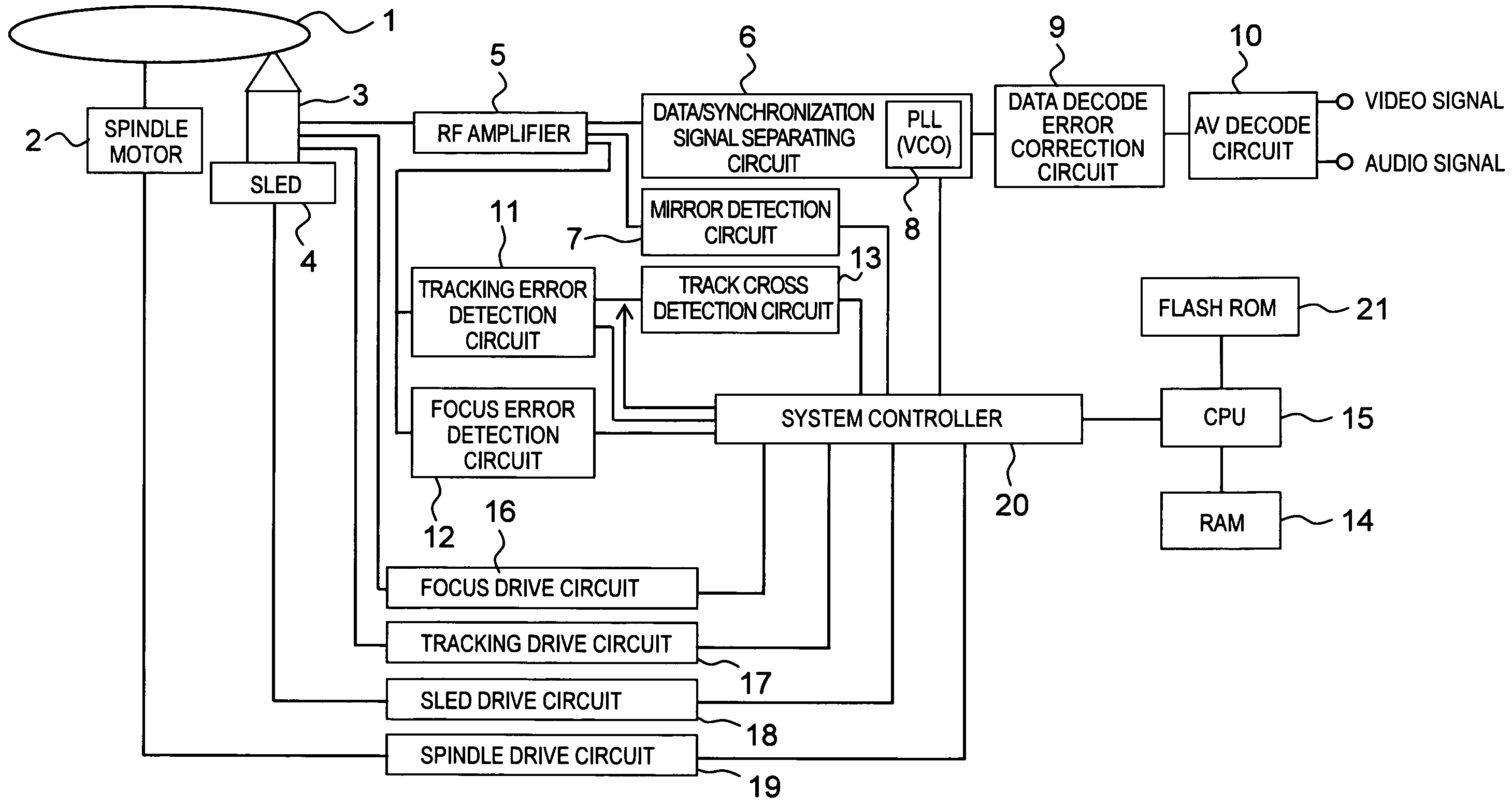
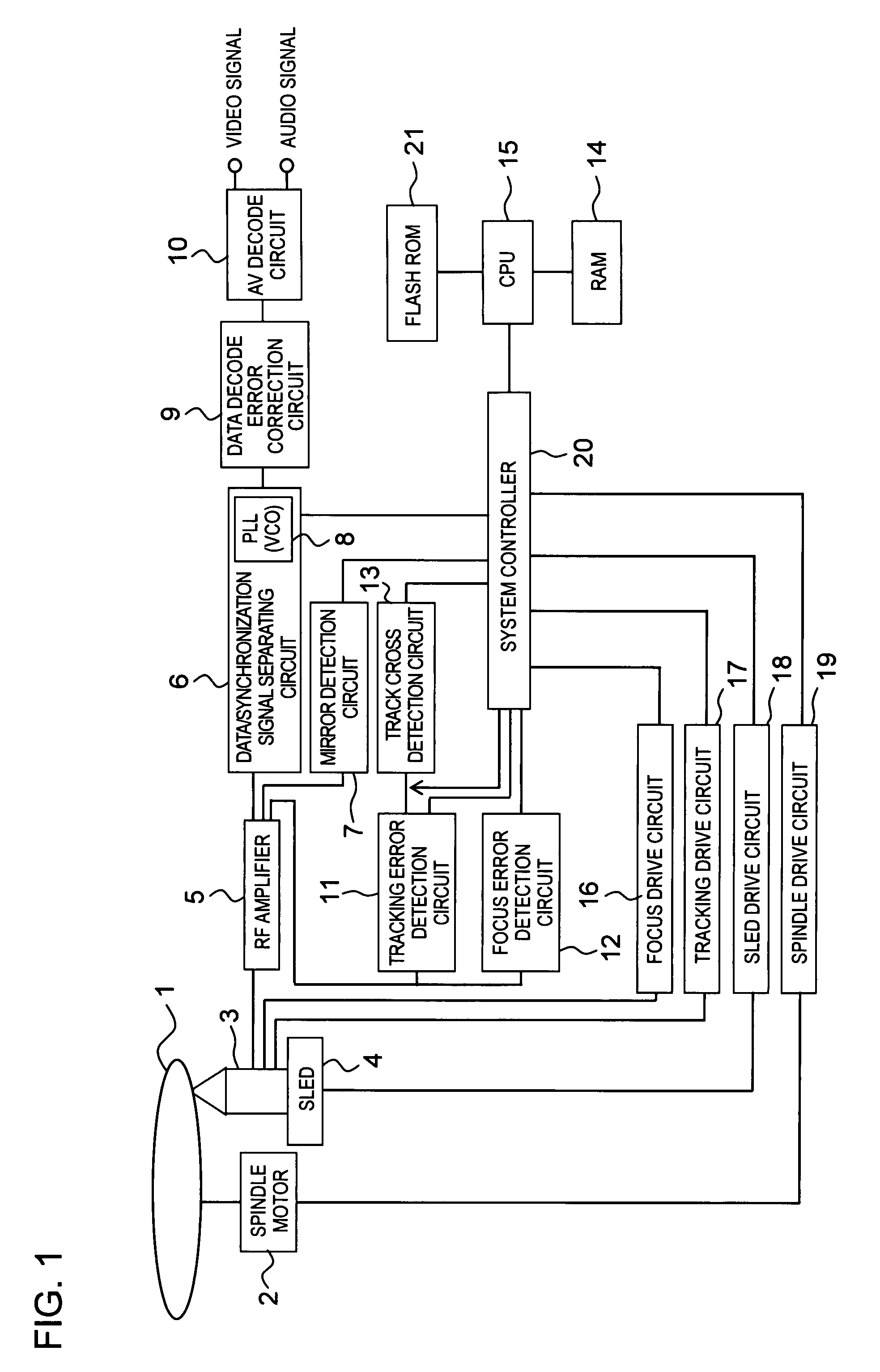
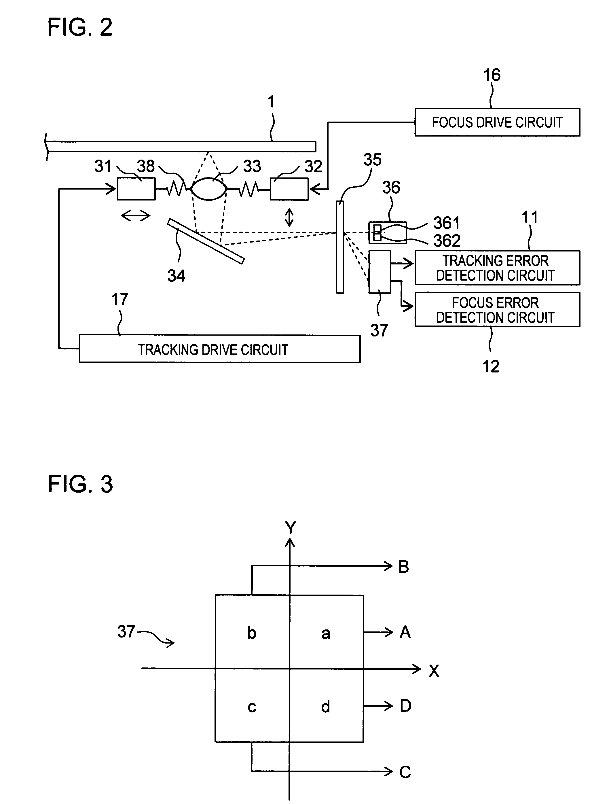
[0032]The system controller 20 of the first embodiment is provided with the following: a DVD signal level acquiring and storing section for moving an objective lens 33 upwards with a DVD laser diode in an on-state so as to acquire levels A, B, C, and D of first, second, third, and fourth detection signals from the photodetector 37 for storage in the RAM 14; a DVD ratio calculating section for calculating a ratio α=(A+D) / (B+C) in a direction of the X-axis from these signal levels; a DVD lens shift correction amount calculating section for calculating the lens shift correction amount for the calculated ratio α based on a correction table indicating a relationship of the ratio and the lens shift correction amount when the ratio α exceeds a predetermined value; a DVD lens shift section for controlling a tracking servo section in accordance with the lens shift correction amount so as to shift the objective lens 33 in the direction of the X-axis when the ratio α exceeds the predetermined ...
second embodiment
[0061]The system controller 20 of a second embodiment is provided with the following: a CD signal level acquiring and storing section for moving the objective lens 33 upwards with the DVD laser diode 361 turned off and the CD laser diode 362 turned on, and acquiring the levels of the first, second, third, and fourth detection signals A, B, C, and D from the four segment photodetector 37 for storage in the RAM 14; a CD ratio calculating section for calculating a ratio α=(A+D) / (B+C) in the direction of the X-axis from these signal levels; a CD lens shift correction amount calculating section for calculating a lens shift correction amount for the calculated ratio α based on a correction table indicating a relationship of the ratio and the lens shift correction amount when the ratio α exceeds a predetermined value; a CD lens shift section for controlling the tracking servo section in accordance with the lens shift correction amount that is calculated so as to shift the objective lens 33...
third embodiment
[0073]FIG. 8 is a timing chart illustrating how a search operation (an operation where levels of the detection signals A, B, C, and D from the four segment photodetector are acquired by the system controller while moving the objective lens in an upward direction) with the DVD laser diode or the CD laser diode of the optical amplifier in an on state is initially added one time, and illustrates each step thereafter up to the focus-on state being achieved in a
[0074]The system controller 20 of the third embodiment is provided with the following: a DVD signal level acquiring and storing section for raising the objective lens 33 upwards with the CD laser diode 362 turned off and the DVD laser diode 361 turned on and acquiring the levels of the first, second, third, and fourth detection signals A, B, C, and D from the four segment photodetector 37 for storage in the RAM 14; a DVD ratio calculating section for calculating a ratio α=(A+D) / (B+C) in a direction of the X-axis from these signal ...
PUM
| Property | Measurement | Unit |
|---|---|---|
| frequency | aaaaa | aaaaa |
| width | aaaaa | aaaaa |
| reflectance | aaaaa | aaaaa |
Abstract
Description
Claims
Application Information
 - R&D Engineer
- R&D Manager
- IP Professional
- Industry Leading Data Capabilities
- Powerful AI technology
- Patent DNA Extraction
Browse by: Latest US Patents, China's latest patents, Technical Efficacy Thesaurus, Application Domain, Technology Topic, Popular Technical Reports.
© 2024 PatSnap. All rights reserved.Legal|Privacy policy|Modern Slavery Act Transparency Statement|Sitemap|About US| Contact US: help@patsnap.com