
Portable power supply module with automatic winding mechanism

a technology of power supply module and winding mechanism, which is applied in the direction of secondary cell servicing/maintenance, cell components, coupling device connections, etc., can solve the problems of increasing space and burden, increasing the risk of loss, and complicated functions of portable electronic equipment, so as to reduce malfunction and facilitate carrying

Inactive Publication Date: 2010-07-13
FORMOSA ELECTRONICS IND INC
View PDF8 Cites 32 Cited by
  • Summary
  • Abstract
  • Description
  • Claims
  • Application Information

AI Technical Summary

Benefits of technology

Enables rapid charging of various electronic devices with reduced risk of damage and improved portability by automatically winding the connection line back into the module after use, minimizing space occupation and preventing external damage.

Problems solved by technology

Nowadays, portable electronic equipment has a variety of functions and is complicated.
The most important issue is how to solve the problem of providing electrical power at power exhaustion and recharging the batteries rapidly and conveniently.
The use of auxiliary power supply equipment will increase the space and burden of weight that cause inconveniences.
Therefore, it is possibly happened that the electronic equipments have the same or different functions, and they may require different specifications of charging devices or different interfaces that do not allow them to use the same charging devices.
Under the circumstances, it usually results that users have to prepare additional rechargeable batteries and charging devices to meet the requirements of different equipments, which produce the problems of occupying space and causing inconvenience.
The first design with separable connection line causes a trouble of carrying that can increase the risk of loss, the occupying space of carrying and a chore of categorizing parts.
The second design of connecting the charging device to the connection line has the least risk of loss, but it has the damages to the connecting point of the connection line and charging device due to pressing or accidental pull.

Method used


Image

  • Portable power supply module with automatic winding mechanism
  • Portable power supply module with automatic winding mechanism
  • Portable power supply module with automatic winding mechanism

Examples


Embodiment Construction

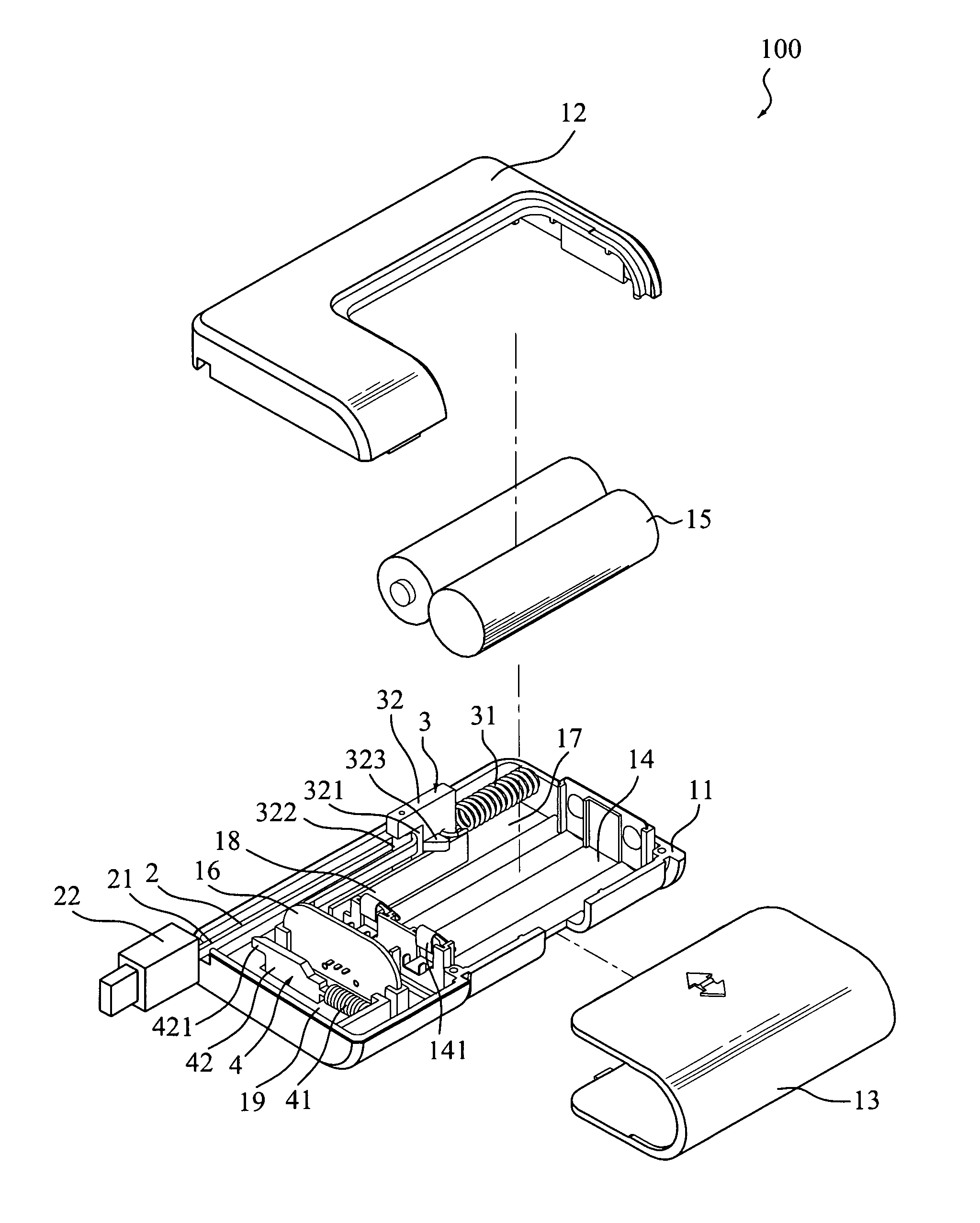
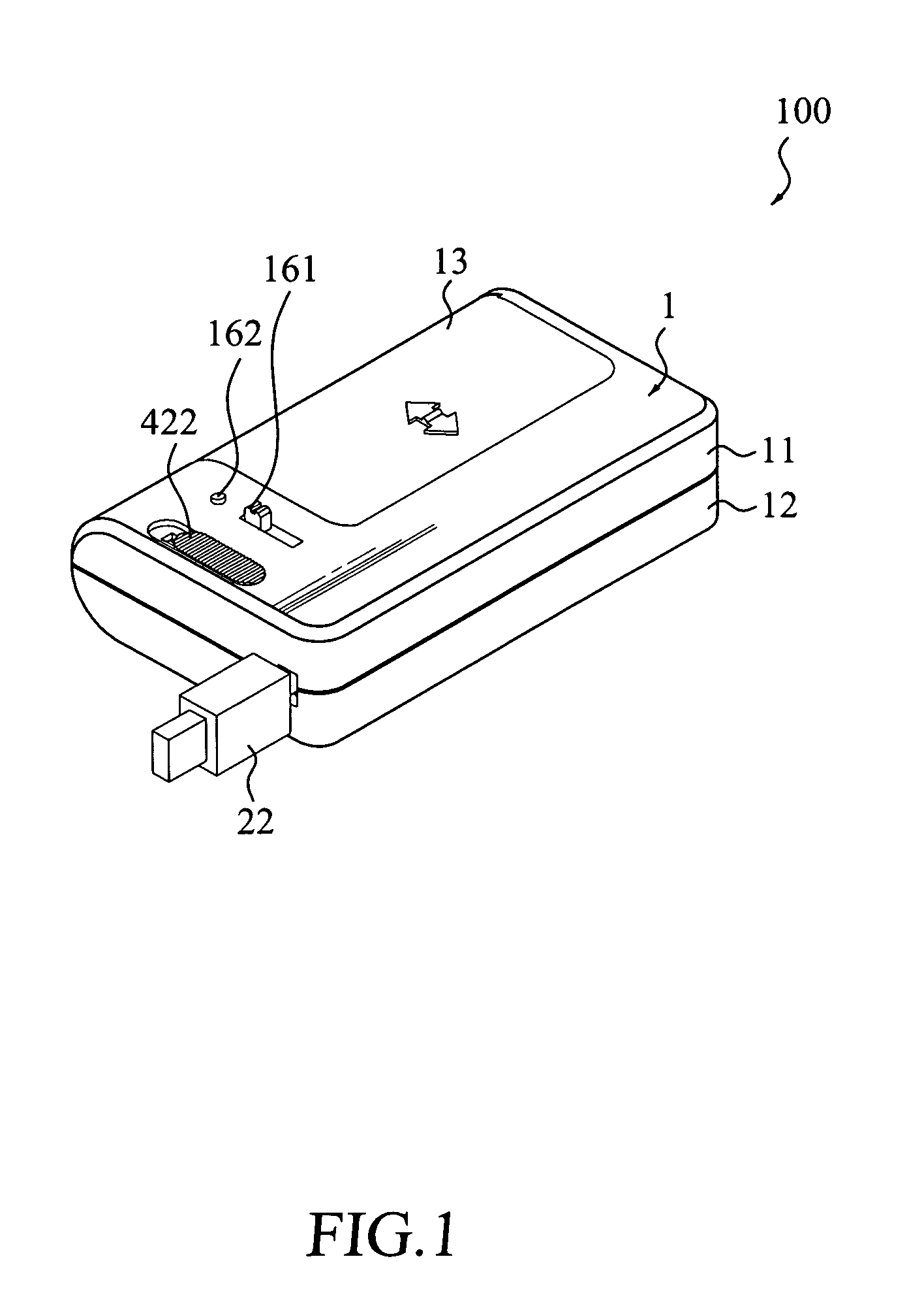
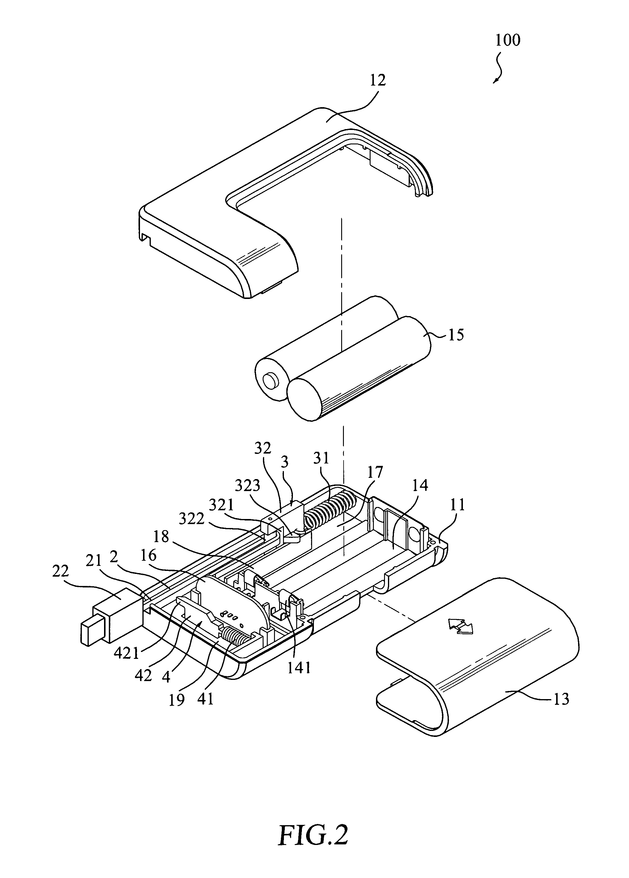
[0020]Referring to FIGS. 1 and 2, FIG. 1 shows a perspective view of a portable power supply module with automatic winding mechanism according to a preferred embodiment of the present invention, and FIG. 2 shows an exploded perspective view of the preferred embodiment of the present invention. As shown in the drawings, a portable power supply module 100 constructed according to the present invention comprises a shell body 1. The shell body 1 comprises a rigid base 11, a lid 12, and a sleeve 13, wherein the lid 12 can be correspondingly fastened to the base 11 and then the sleeve 13 can also correspondingly and laterally be put to the base 11 and the lid 12 to form the shell body 1.

[0021]The internal part of the shell body 1 is formed with a battery room 14 comprising at least one set of conductive contact plates 141. The battery room 14 may accommodate two batteries 15 to supply electrical power via the conductive contact plates 141 which are connected to a circuit board 16. The cir...


PUM


Abstract

A portable power supply module with winding mechanism is disclosed, which includes a shell body, a battery room formed at the shell body for accommodating at least one battery, a connection line, a pulling compartment in the shell body for accommodation of the connection line and a winding mechanism located in the pulling compartment. At least one set of conductive contact plates are provided and are connected to a circuit board to a supply power from the battery. A first end of the connection line is connected to the circuit board and a second end of the connection line is connected to an output connector. When the connection line is pulled and the winding mechanism slides forward to extend the connection line. When the portable power supply module is not in use, the winding mechanism pulls and retracts the connection body in the shell body.

Description

FIELD OF THE INVENTION[0001]The present invention relates to a portable power supply module, especially to a portable power supply module having a winding mechanism that can automatically wind a connection line.BACKGROUND OF THE INVENTION[0002]With the rapid development of technology in the society today, people have a variety of portable electronic equipment, such as cell phones, notebook computers, walkmans, portable memory hardware, PDAs, digital cameras, etc., that have been often used by people in different industries and become indispensable in our lives. Nowadays, portable electronic equipment has a variety of functions and is complicated. The most important issue is how to solve the problem of providing electrical power at power exhaustion and recharging the batteries rapidly and conveniently. Some prior arts provide solutions to the problem.[0003]Taiwan Invention Patent No. 200711256 discloses a portable charging device that is installed in a notebook computer or other port...

Claims


Application Information

Patent Timeline
Patent Type & Authority Patents(United States)
IPC IPC(8): H02J7/00
CPCH01R13/72H01M10/425H01M2/1055H01M50/213Y02E60/10
Inventor WU, MICHAEL
Owner FORMOSA ELECTRONICS IND INC
Learn More