
Networked electronic ordnance system

a technology of electronic ordnance and networked devices, which is applied in the direction of lighting and heating apparatus, electric fuzes, combustion processes, etc., can solve the problems of increased equipment and equipment costs, so as to reduce or eliminate the surge currents in the network

Inactive Publication Date: 2010-07-13
MCCORMICK SELPH
View PDF52 Cites 11 Cited by
  • Summary
  • Abstract
  • Description
  • Claims
  • Application Information

AI Technical Summary

Benefits of technology

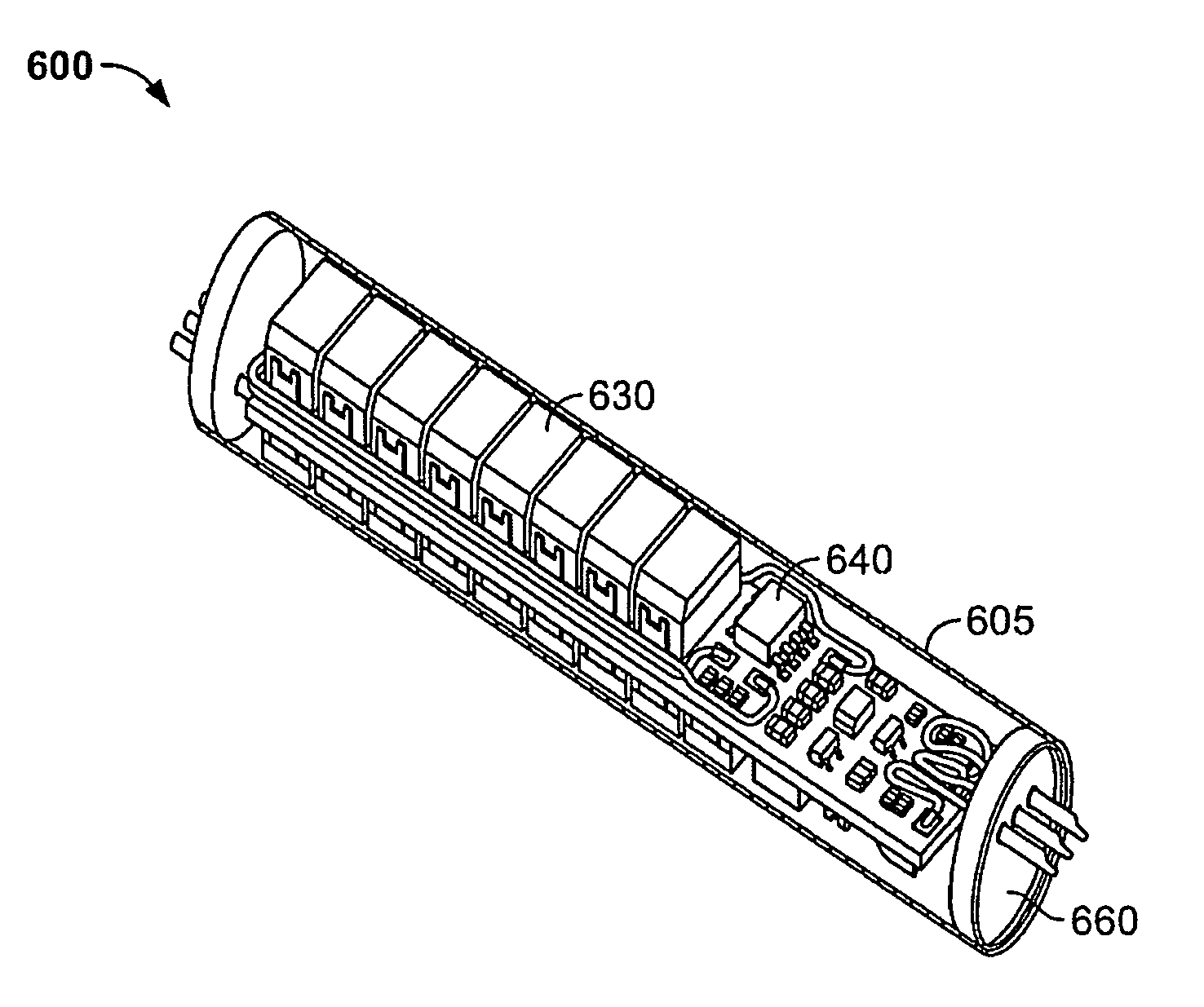
[0012]In another embodiment, both digital and analog fire control conditions are met before a pyrotechnic device can be fired. In an embodiment, each pyrotechnic device includes an energy reserve capacitor (ERC) which stores firing energy upon arming. By storing firing energy within each pyrotechnic device, surge currents in the network are reduced or eliminated, thereby eliminating the need for separate ordnance system batteries or power circuits. In an embodiment, a plurality of initiators are packaged together on a single substrate and networked together via that substrate.

Problems solved by technology

However, the use of additional pyrotechnic devices carries with it the burden of additional infrastructure within the vehicle or system using these devices.
As the number of pyrotechnic devices in a vehicle or system increases, several other things increase as well, such as cabling length, cable quantity, weight, number of parts, power usage, system complexity, manufacturing time and system cost.
In an environment such as a rocket or missile, weight and volume are at a premium, and an increase in pyrotechnic system weight and volume presents packaging and weight management problems which may require significant engineering time to solve.
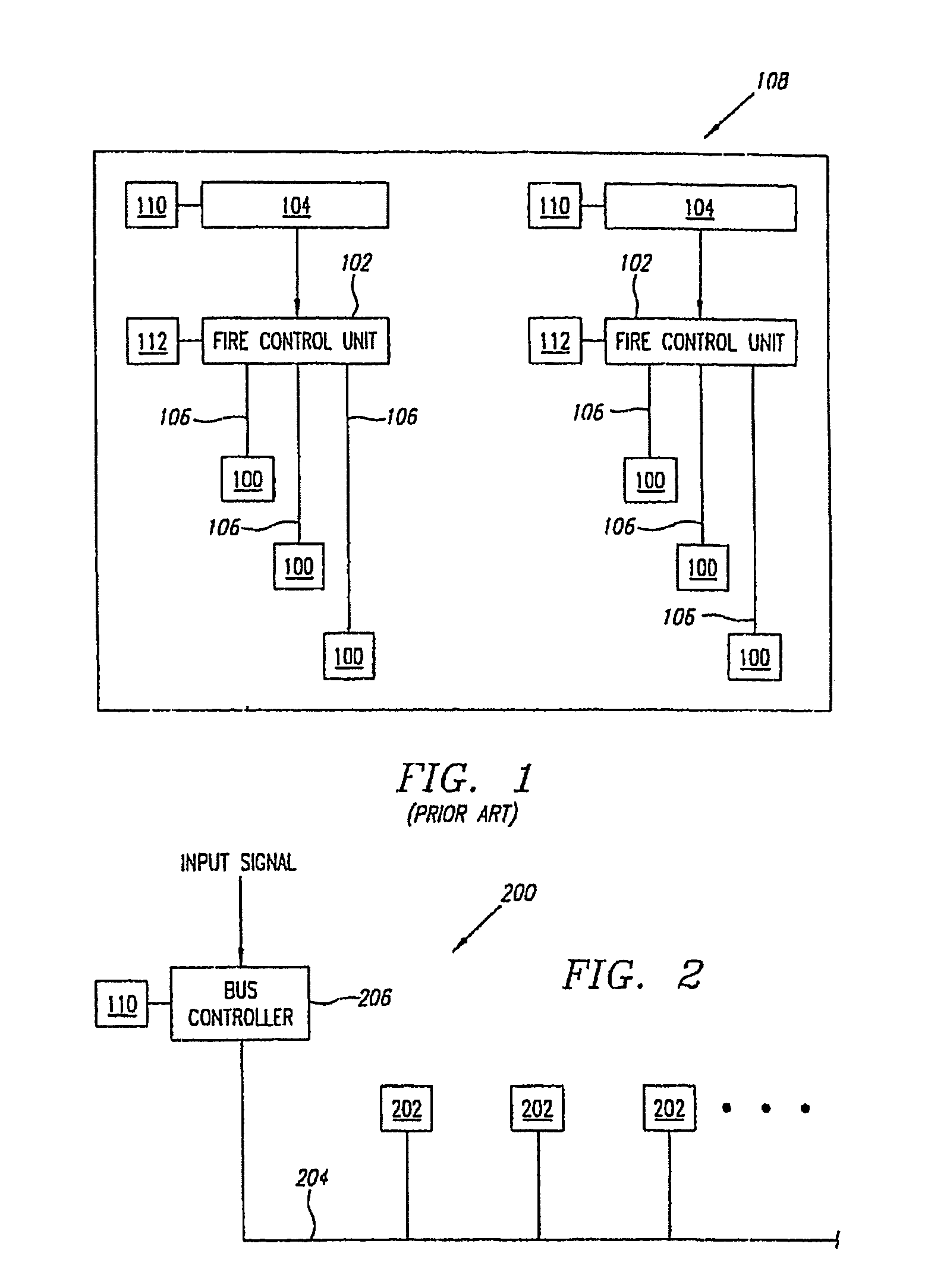
Typically, these devices are connected in an inefficient branching configuration.
If the cable were not shielded, these sources of interference could potentially interfere with the operation of one or more of the pyrotechnic devices 100.
In the aggregate, the large number of high-power shielded cables 106 required for the branching configuration of the prior art are heavy and occupy significant volume, resulting in weight and packaging difficulties within an aircraft, spacecraft, missile, launch vehicle or other application where weight and space are at a premium.
This separate power system is required because surge currents occur in the power cabling when a pyrotechnic device is fired, potentially interfering with the avionics system.
Due to the high delivery current required, the ordnance system batteries 112 are typically large and heavy.

Method used


Image

  • Networked electronic ordnance system
  • Networked electronic ordnance system
  • Networked electronic ordnance system

Examples


Embodiment Construction

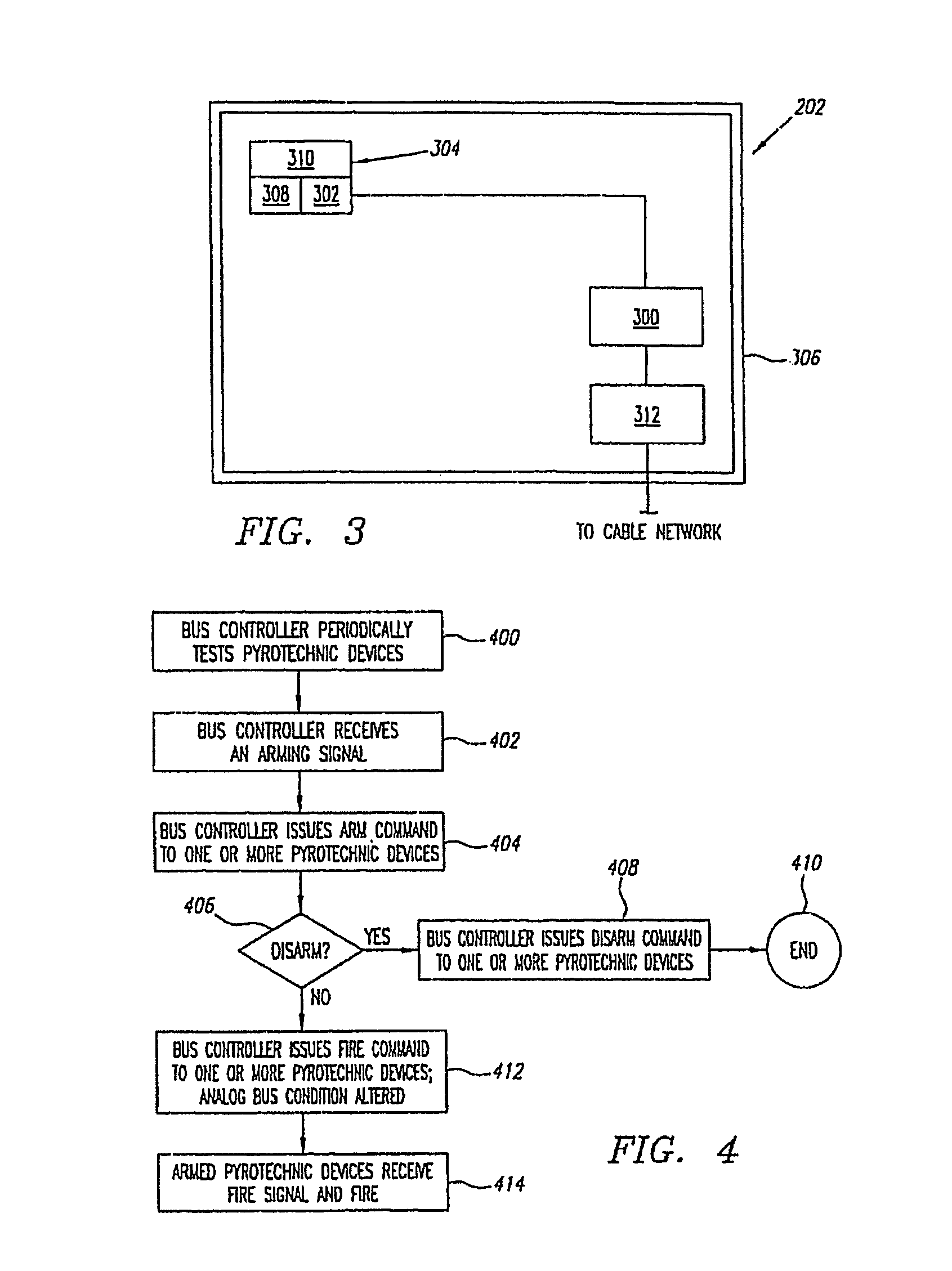
[0021]Referring to FIG. 2, a preferred embodiment of a networked electronic ordnance system 200 is shown. The networked electronic ordnance system 200 includes a number of pyrotechnic devices 202 interconnected by a cable network 204, which may be referred to as a bus. The cable network 204 also connects the pyrotechnic devices 202 to a bus controller 206. In a preferred embodiment, the cable network 204 is formed from at least one two-wire cable which provides low voltage and low current power, and control signals, to the pyrotechnic devices 202. As used in this document, the word “cable” may refer to multiple strands of associated wire, a single wire, or other appropriate conductors, such as flexible circuit boards. Electric power transmission and signal transmission preferably both occur over the same cable in the cable network 204, thereby eliminating any need to provide separate power and signal cables. In a preferred embodiment, the cable network 204 is built from twisted shie...


PUM


Abstract

A networked electronic ordnance system and method for controlling a variety of pyrotechnic devices at different energy levels include a bus controller controlling at least one pyrotechnic device operating at a first energy level and a smart connector adapting at least one pyrotechnic device operating at a second energy level to control by the bus controller. The smart connector may also include a plurality of capacitors for firing the pyrotechnic device(s). In an embodiment, at least one pyrotechnic device operating at a first energy level and at least one pyrotechnic device operating at a second level include a logic device have a unique identifier. The smart connector may also include an energy reserve capacitor and an emitter follower circuit electrically connected to a logic device. Additionally, the smart connector may be connected to an initiator for firing at least one pyrotechnic device at the second energy level.

Description

RELATED APPLICATIONS[0001]This application is a continuation-in-part of U.S. patent application Ser. No. 09 / 656,325, filed on Sep. 6, 2000 now U.S Pat. No. 7,644,661, with inventors Michael Diamond and Steven Nelson, entitled “Networked Electronic Ordnance System.”FEDERALLY SPONSORED RESEARCH OR DEVELOPMENT[0002][Not Applicable]MICROFICHE / COPYRIGHT REFERENCE[0003][Not Applicable]BACKGROUND OF THE INVENTION[0004]The field of this invention relates to a networked system of pyrotechnic devices.[0005]Pyrotechnic devices play an increasingly important role in aerospace vehicles and systems such as rockets, aircraft and spacecraft. As an example, the number of pyrotechnic devices used on a typical missile has increased over the years from less than ten to as many as two hundred or more. The additional pyrotechnic devices may be used for several purposes. For example, multiple lower-powered initiators may be used in place of a single higher-powered initiator to provide flexibility in the a...

Claims


Application Information

Patent Timeline
Patent Type & Authority Patents(United States)
IPC IPC(8): F23Q21/00
CPCF42C15/40F42D1/05
Inventor NELSON, STEVEN D.DIAMOND, MICHAEL N.
Owner MCCORMICK SELPH
Learn More