
Image recognition method and image recognition apparatus

a recognition method and image recognition technology, applied in image data processing, instruments, image analysis, etc., can solve the problems of large method, and large amount of operation, and achieve the effect of extremely reducing the amount of operations

Inactive Publication Date: 2010-07-06
PANASONIC CORP
View PDF73 Cites 5 Cited by
  • Summary
  • Abstract
  • Description
  • Claims
  • Application Information

AI Technical Summary

Benefits of technology

This approach securely extracts desired patterns with a reduced number of operations and enhances precision by correctly distinguishing patterns despite non-uniform lighting, thereby improving the efficiency and accuracy of image recognition.

Problems solved by technology

However, this method has a large problem.
That is, the first problem is a problem of an amount of operation.
Accordingly, the amount of operation becomes very large and the time for the judgement becomes longer.
The second problem is a problem caused by a non-uniformity of a light.
At this time, the pattern 204 and its adjacent background are also lighter, and when a difference from the template is obtained, the difference due to the non-uniformity of the brightness remains involved in all the pixels, and there is a possibility that the judgement is incorrectly made.
The prior art image recognition method and image recognition apparatus are constructed as described above, in which while a processing for eliminating an influence due to non-uniformity of a light can be performed, the amount of operation cannot be reduced, and further an operation for correcting brightness is required, and thereby there is a problem that the processing load becomes more massive.
Moreover, since an actual image is used as a template, the additions of the differences become larger due to an influence of a noise, thereby potentially leading to an incorrect judgement.

Method used


Image

  • Image recognition method and image recognition apparatus
  • Image recognition method and image recognition apparatus
  • Image recognition method and image recognition apparatus

Examples


embodiment 1

[0064]As an example of an image recognition method and an image recognition apparatus according to a first embodiment of the present invention, a process of detecting a microbead (hereinafter, referred to as a bead) of a diameter of 10 μm from a microscope image will be described.

[0065]A target image is designated by the reference numeral 202 shown in FIG. 9, and is a digital image of 1024 pixel width and 768 pixel height in which each pixel has any of 256 gradations as a luminance. As the luminance becomes higher, the luminance value is represented as the higher value. A large number of beads appear in the target image 202, and the purpose is to extract the areas of these beads.

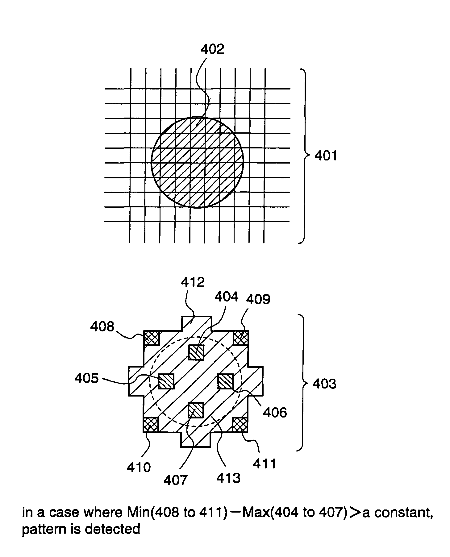
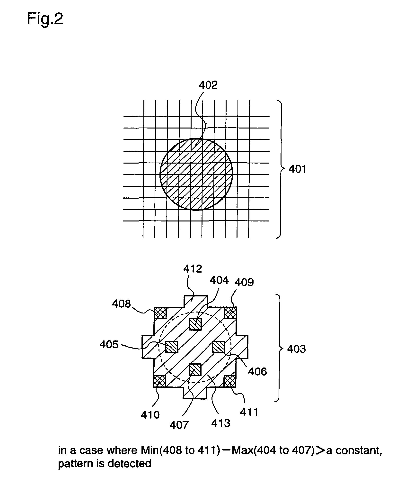
[0066]FIG. 2 illustrates an example for setting a pattern area according to the image recognition method of the first embodiment. In FIG. 2, a reference numeral 401 represents an enlarged vicinity of a bead as the target image in which a bead 402 appears dark. The image is photographed when a light is applie...

embodiment 2

[0082]Next, an image recognition method and an image recognition apparatus according to a second embodiment of the present invention will be described. While in the first embodiment, a conceptual construction and operation according to the present invention is described, a more specific embodiment will be described next.

[0083]FIG. 3 shows a target image. The upper part of FIG. 3 shows a target image 501 photographed by a microscope and a plurality of beads appear inside. The target image 501 is 640 pixels wide and 480 pixels high in the image, and each pixel has any of 256 gradations ranging from 0 to 255. As a frame of reference of the image, the upper left corner is (0, 0), and the right direction is the plus direction of x-axis while the downward direction is the plus direction of y-axis in the image. Thereby, when a pixel in the lower right in the image is represented as a coordinate, it is (639, 479).

[0084]While some hundreds of beads appear in an actual target image, 6 pieces ...

embodiment 3

[0107]Next, an image recognition method and an image recognition apparatus according to a third embodiment of the present invention will be described.

[0108]While in each of the above-described embodiments the pattern presence judgement method in the case of the shape of the discrimination target being round is described, the presence judgement method for the other shapes will be described with reference to the drawings. FIG. 7 illustrates a mask pattern used for detecting the discrimination target having a square shape. A reference numeral 901 represents an outline shape of the square as the discrimination target, and all the areas indicated by the same hatching as that for the part indicated by a lead line 902 are the first pattern areas. Similarly, a reference numeral 903 represents the second pattern area.

[0109]When it is judged whether or not a specific pattern is present in the discrimination target, in a case where the smallest luminance of the luminances contained in the seco...


PUM


Abstract

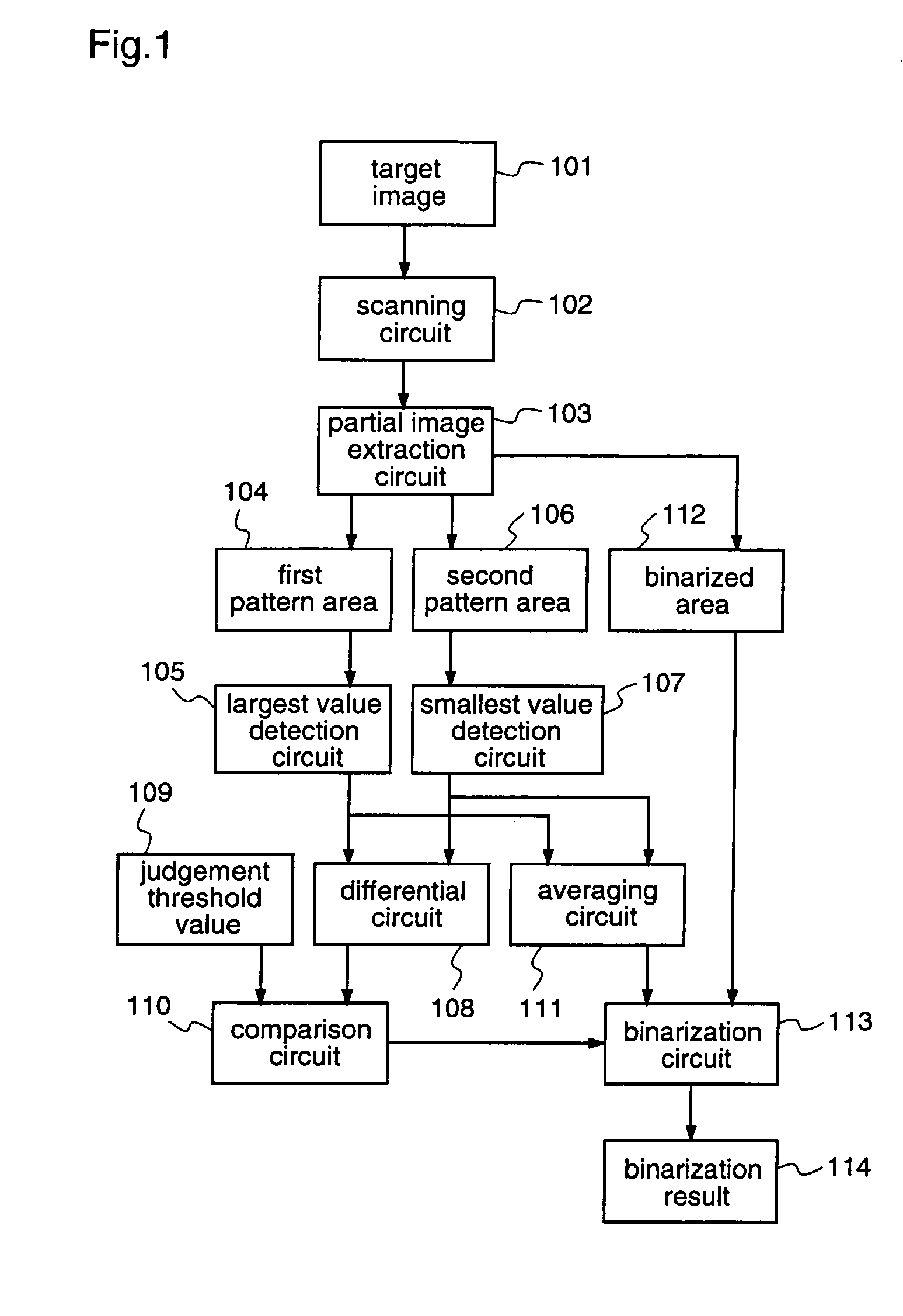
Provided is an image recognition method in which a first pattern area which is set inside a target to be recognized and a second pattern area which is set outside the target are used as a mask pattern. When a comparison circuit judges that a difference obtained by subtracting, by a differential circuit, the largest luminance value in the target image contained in the first pattern area, which is detected by a largest value detection circuit, from the smallest luminance value in the target image contained in the second pattern area, which is detected by the smallest value detection circuit, is larger than a certain offset amount, the matching judgement that a predetermined pattern is present is made. This recognition judgment is performed with the whole target image being scanned.

Description

BACKGROUND OF THE INVENTION[0001]1. Field of the Invention[0002]The present invention relates to a method and an apparatus for performing a characterization with using an optical means and processing an image for recognition, and more particularly, to a technique for photographing a target to be photographed as image data of a plurality of gradations, extracting a target to be noted from the image and performing binarization.[0003]2. Description of the Related Art[0004]Conventionally, various methods for recognizing images have been suggested. The methods are executed for various purposes such as for searching an image for a specific pattern or for checking whether the target detected from the image has a normal shape. While the purposes are various, however, a method in which a target image is compared with a specific template image as a reference in some manner and the resultant is numerically evaluated, and thereby how much the target image matches the template image is checked i...

Claims


Application Information

Patent Timeline
Patent Type & Authority Patents(United States)
IPC IPC(8): G06K9/00G06K9/62G06K9/68G06T7/00G01B11/00
CPCG06K9/6212G06V10/758
Inventor TAKARADA, SHINICHI
Owner PANASONIC CORP
Learn More