
Internet-based system for monitoring vehicles

a technology of vehicle monitoring and internet-based system, which is applied in the direction of instruments, machines/engines, mechanical equipment, etc., can solve the problems that manufacturers also include complex electronic systems in their vehicles

Inactive Publication Date: 2010-06-29
VERIZON PATENT & LICENSING INC
View PDF185 Cites 82 Cited by
  • Summary
  • Abstract
  • Description
  • Claims
  • Application Information

AI Technical Summary

Benefits of technology

[0015]The invention has many advantages. In particular, wireless transmission of data from a vehicle, followed by analysis and display of these data using a web site hosted on the internet, makes it possible to diagnose the performance of a vehicle in real-time from virtually any location that has internet access. This ultimately means the problems with the vehicle can be efficiently diagnosed, and in some cases predicted before they actually occur. Moreover, data from the vehicle can be queried and analyzed while the vehicle is actually in use to provide a relatively comprehensive diagnosis that is not possible using a conventional scan tool. An internet-based system for vehicle diagnoses can also be easily updated and made available to a large group of users simply by updating software on the web site. In contrast, a comparable updating process for a series of scan tools can only be accomplished by updating the software on each individual scan tool.
[0016]The wireless appliance used to access and transmit the vehicle's data is small, low-cost, and can be easily installed in nearly every vehicle with an OBD-II connector in a matter of minutes. It can also be easily transferred from one vehicle to another, or easily replaced if it malfunctions.
[0017]An in-vehicle wireless appliance can also collect data that is not accessible using a scan tool. For example, data that indicates a vehicles performance can be collected while the vehicle is actually driven. Scan tools, in contrast, can only collect data in a vehicle service bay. Service technicians, for example, can analyze DTCs during repair of the vehicle. The system described herein makes also makes data available in real-time, thereby allowing the technicians to order parts and schedule resources for service appointments before the vehicle is actually brought into the dealership.

Problems solved by technology

Some vehicle manufacturers also include complex electronic systems in their vehicles to access and analyze some of the above-described data.

Method used


Image

  • Internet-based system for monitoring vehicles
  • Internet-based system for monitoring vehicles
  • Internet-based system for monitoring vehicles

Examples


Embodiment Construction

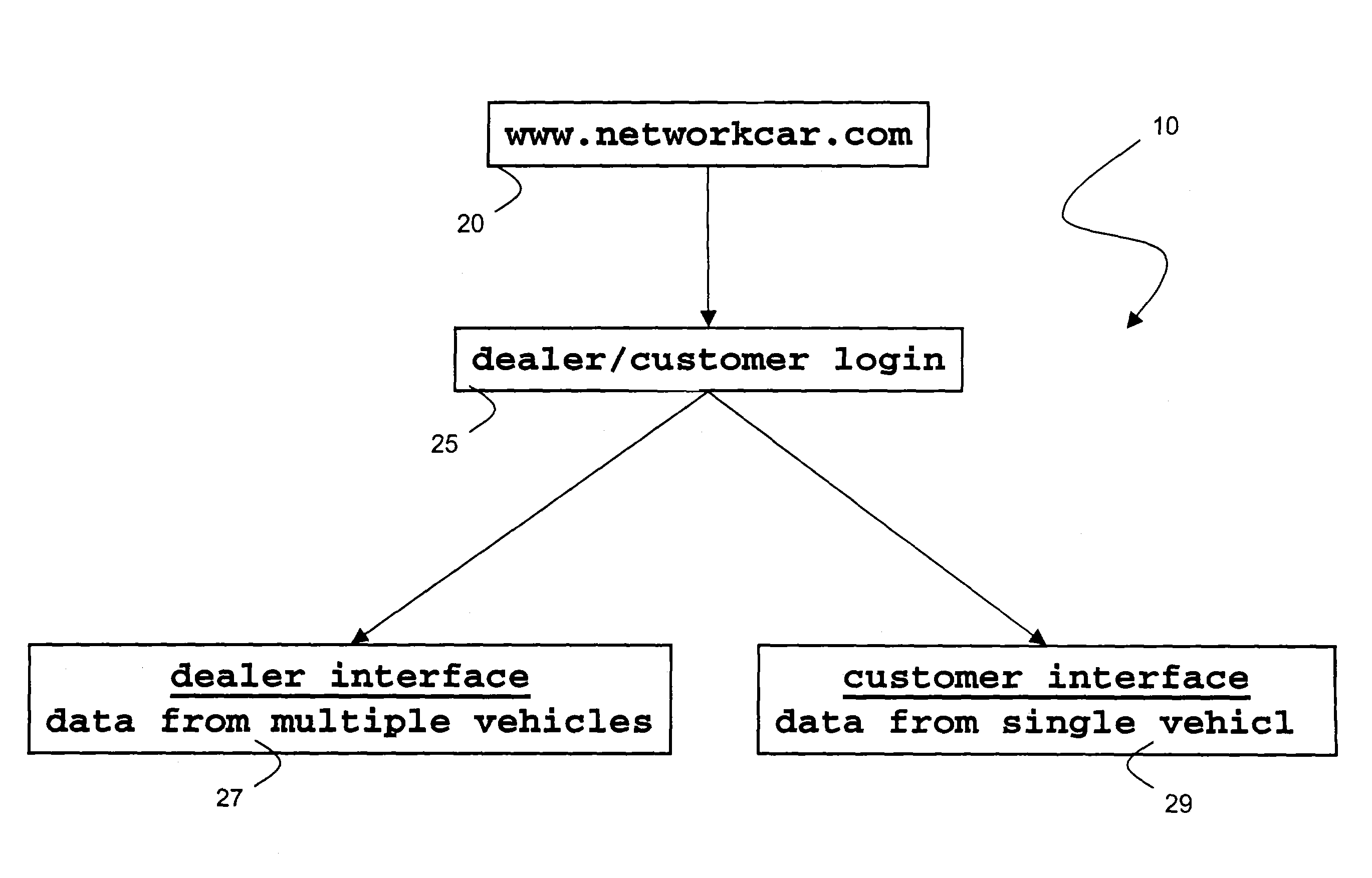
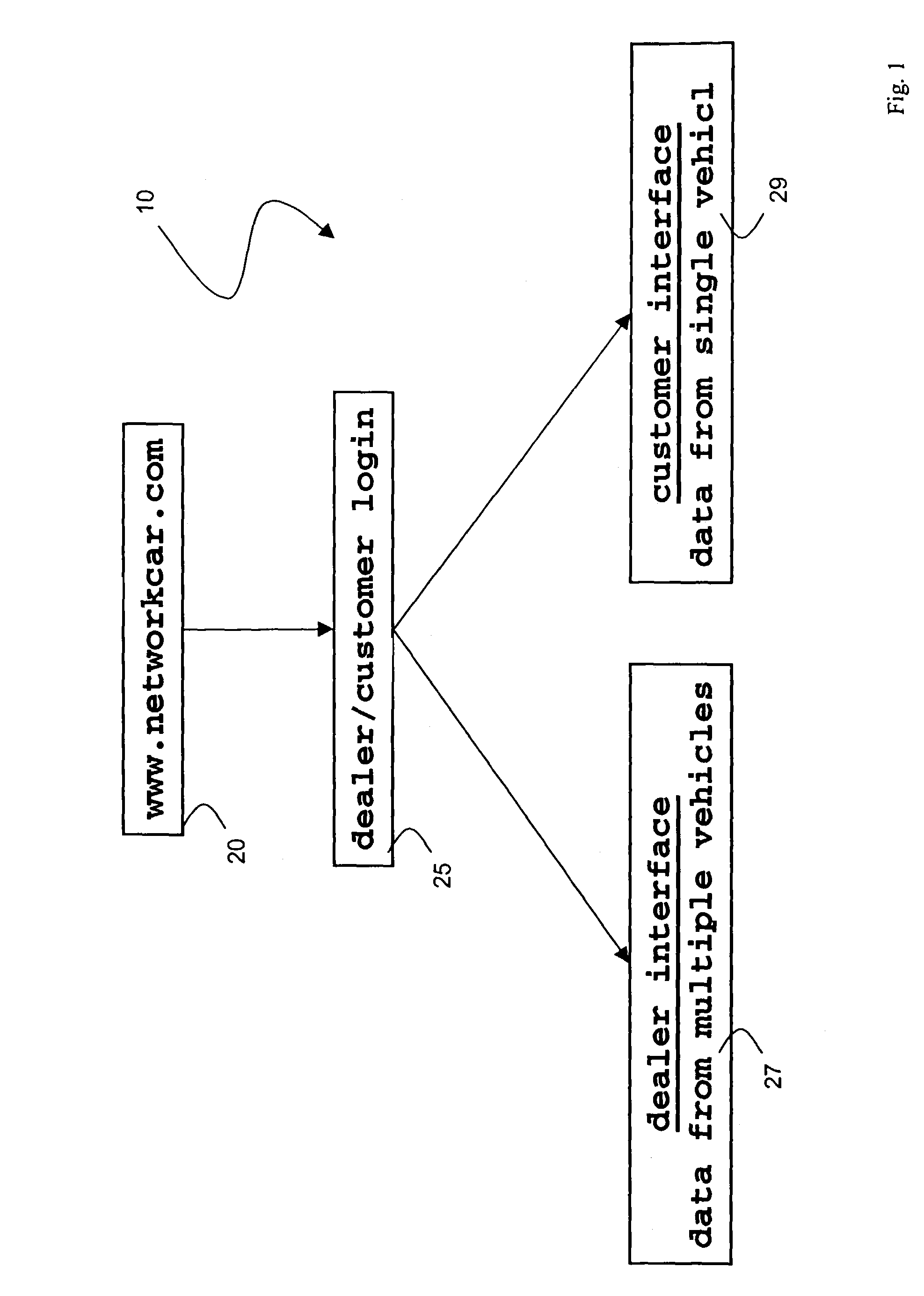
[0029]FIG. 1 shows a schematic drawing of a login process 10 for a website 20 that displays diagnostic data for a series of ‘customer’ vehicles associated with a vehicle ‘dealership’. Within each vehicle is a wireless appliance that retrieves data from the vehicle's engine computer, and then sends these data, formatted in a data packet, wirelessly through a network. The data eventually are transferred from the network to the website 20 where they are formatted and displayed and processed as described below.

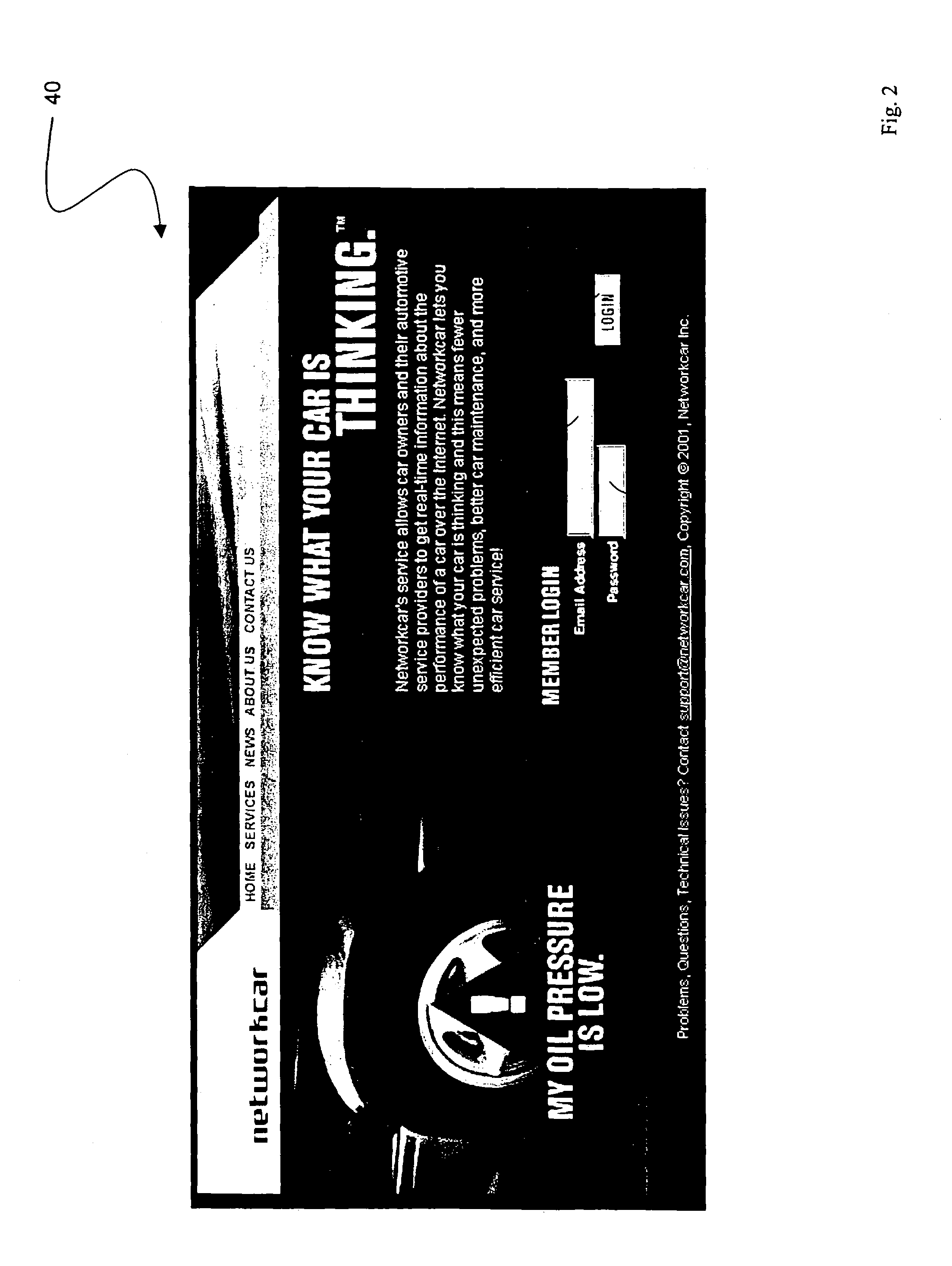
[0030]A user ‘logs’ into the website 20 by entering a username and password that, once entered, are compared to a database associated with the website. The comparison determines if the user is a dealer or a customer. If the user is determined to be a dealer, the website renders a dealer interface 27 that contains, e.g., diagnostic information for each vehicle purchased from the particular dealership. Users viewing the dealer interface 27 do not have access to data corresponding to...


PUM


Abstract

The invention provides a method for monitoring a vehicle that features the steps of: 1) generating a data packet including vehicle data retrieved from the vehicle using a wireless appliance; 2) transmitting the data packet over an airlink with the wireless appliance so that the data packet passes through a network and to a host computer system; 3) processing the data packet with the host computer system to generate a set of data; and 4) displaying the set of data on a web page hosted on the internet.

Description

[0001]This application is a continuation application of U.S. patent application Ser. No. 09 / 804,888, filed Mar. 13, 2001 now abandoned, the contents of which are incorporated herein by reference.FIELD OF THE INVENTION[0002]The present invention relates to use of an internet-based system for monitoring a vehicle's performance.BACKGROUND OF THE INVENTION[0003]The Environmental Protection Agency (EPA) requires vehicle manufacturers to install on-board diagnostics (OBD-II) for monitoring light-duty automobiles and trucks beginning with model year 1996. OBD-II systems (e.g., microcontrollers and sensors) monitor the vehicle's electrical and mechanical systems and generate data that are processed by a vehicle's engine control unit (ECU) to detect any malfunction or deterioration in the vehicle's performance. Most ECUs transmit status and diagnostic information over a shared, standardized electronic buss in the vehicle. The buss effectively functions as an on-board computer network with ma...

Claims


Application Information

Patent Timeline
Patent Type & Authority Patents(United States)
IPC IPC(8): G01M17/00G07C5/00
CPCG07C5/008G07C5/006F02M25/0818F02M25/0827Y02T10/84
Inventor LOWREY, LARKIN HILLBANET, MATTHEW J.LIGHTNER, BRUCEBORREGO, DIEGOMYERS, CHUCK
Owner VERIZON PATENT & LICENSING INC
Learn More