
Multi-cyclone dust separating apparatus of vacuum cleaner

a technology of dust separating apparatus and vacuum cleaner, which is applied in the direction of auxillary pretreatment, cleaning filter means, separation processes, etc., can solve the problems of reducing the efficiency of dust collection, affecting the cleaning efficiency of dust collection apparatus, and difficulty in maintaining dust collection apparatus, etc., to achieve convenient dumping of dust collected, improve separating efficiency, and facilitate the cleaning, maintenance and repair of components

Inactive Publication Date: 2010-06-29
SAMSUNG GWANGJU ELECTRONICS CO LTD
View PDF11 Cites 34 Cited by
  • Summary
  • Abstract
  • Description
  • Claims
  • Application Information

AI Technical Summary

Benefits of technology

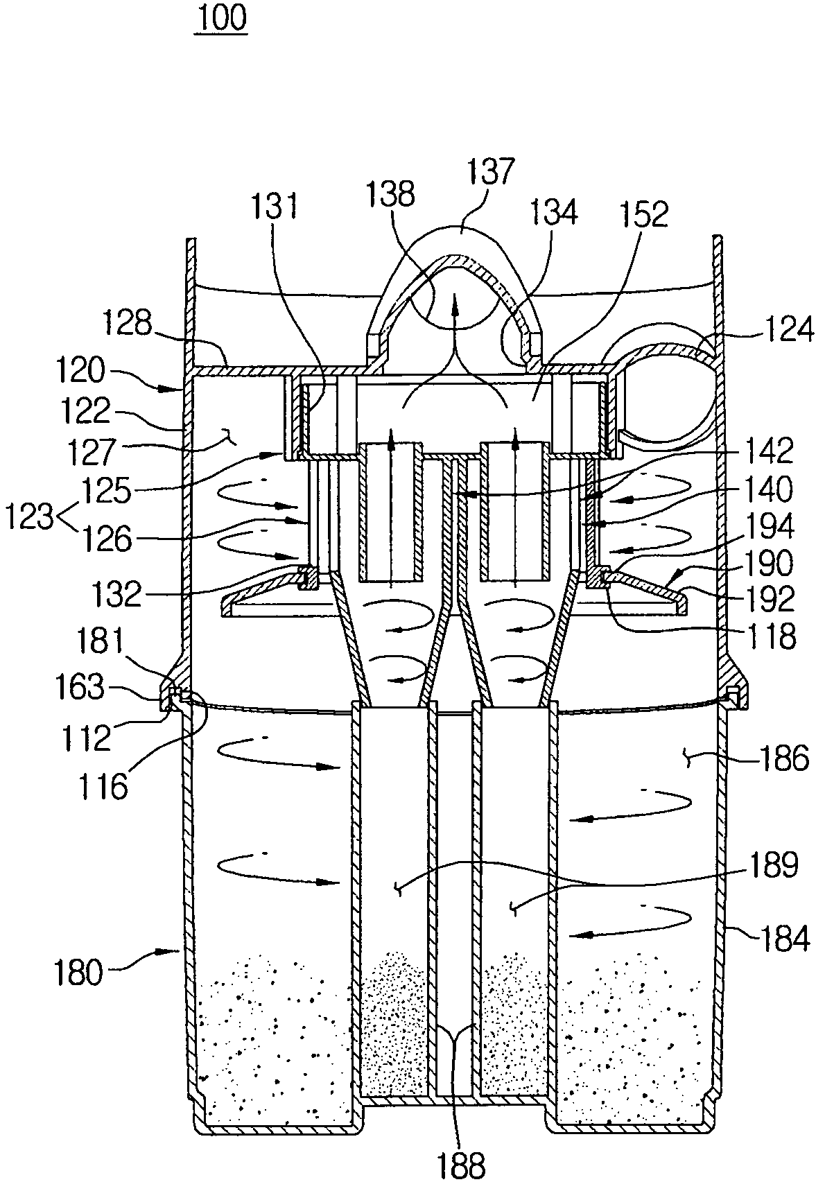
"The present disclosure provides a multi-cyclone dust separating apparatus that can easily dump dust collected therein while being compact with a small outer diameter. The apparatus also improves separating efficiency for minute dust in a second cyclone unit while being compact. Additionally, the apparatus facilitates cleaning, maintenance, and repair for components therein. The apparatus includes a first cyclone unit, a second cyclone unit, and a dust bin. The first cyclone unit includes a cylindrical element with a first air inlet and a cylindrical element with a first air outlet. The second cyclone unit includes a plurality of cyclones, each with a second air inlet for drawing in the air from which the dust is separated in the first cyclone chamber. The dust bin includes a first dust collecting chamber for collecting the dust separated by the first cyclone unit and a plurality of second dust collecting chambers for collecting the dust separated by the second cyclone unit. The second cyclone unit is disposed in the cylindrical element of the first cyclone unit and the plurality of second dust collecting chambers of the dust bin is separately formed and connected with the corresponding cyclones of the second cyclone unit, respectively. The first air outlet of the cylindrical element of the first cyclone unit is adapted to face the second air inlets of the plurality of cyclones. The first cyclone unit may also include a grill member and a skirt member. The second cyclone unit may also include an air stagnating space. The dust bin may also include a second outer tub and a plurality of cylinder members. The technical effects of the present disclosure include improved separating efficiency for minute dust, compact design, and easy maintenance."

Problems solved by technology

However, because the air to the second cyclone is drawn in through a single air inlet, a whirling force of the second cyclone is weakened.
Also, because the first and the second cyclone are neither separated nor subdivided into respective components, cleaning the inner parts of the dust collecting apparatus, maintaining the dust collecting apparatus, and repairing the dust collecting apparatus is difficult.

Method used


Image

  • Multi-cyclone dust separating apparatus of vacuum cleaner
  • Multi-cyclone dust separating apparatus of vacuum cleaner
  • Multi-cyclone dust separating apparatus of vacuum cleaner

Examples


Embodiment Construction

[0028]Hereinafter, a multi-cyclone dust separating apparatus according to exemplary embodiments of the present disclosure will now be described in greater detail with reference to the accompanying drawings.

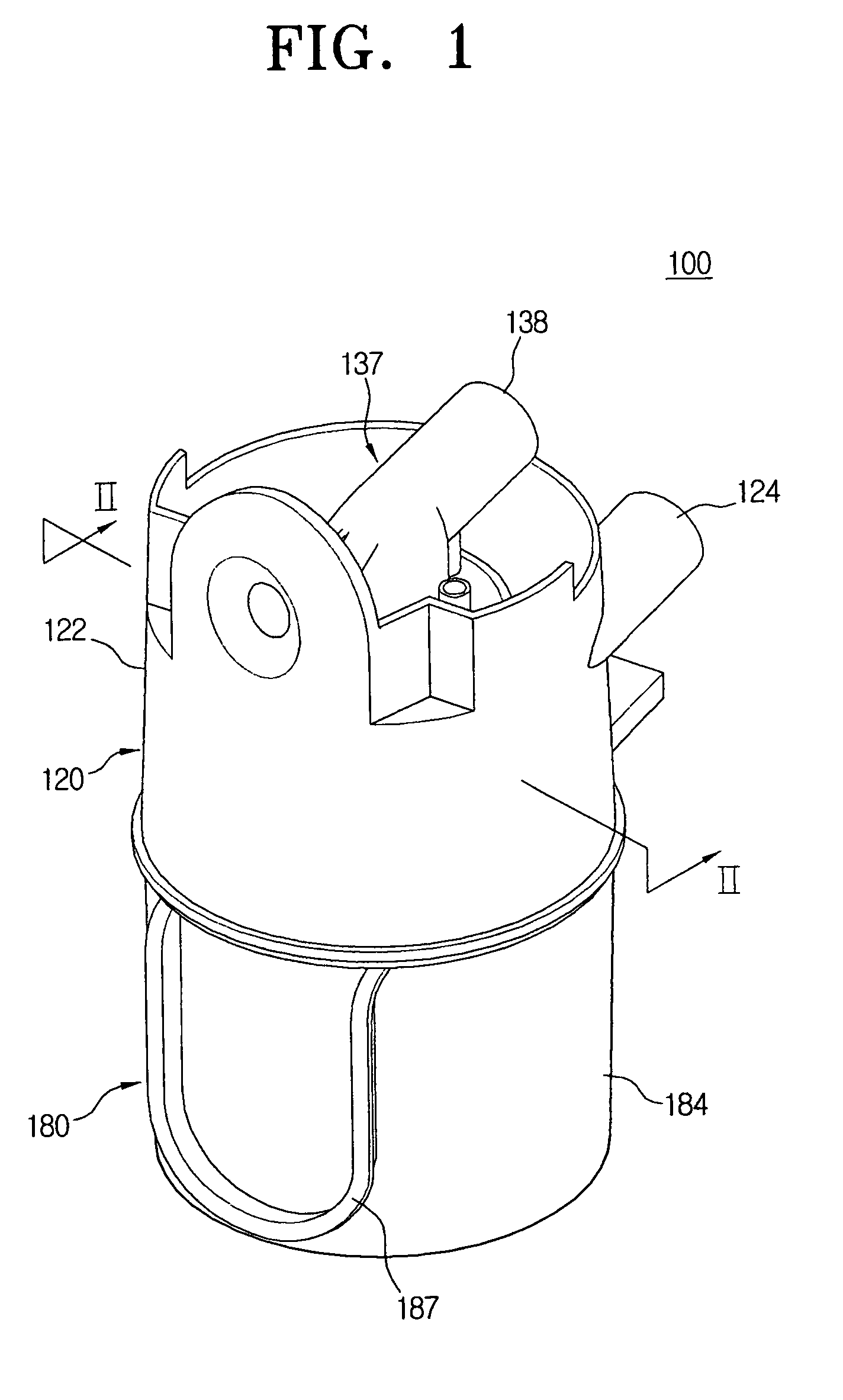
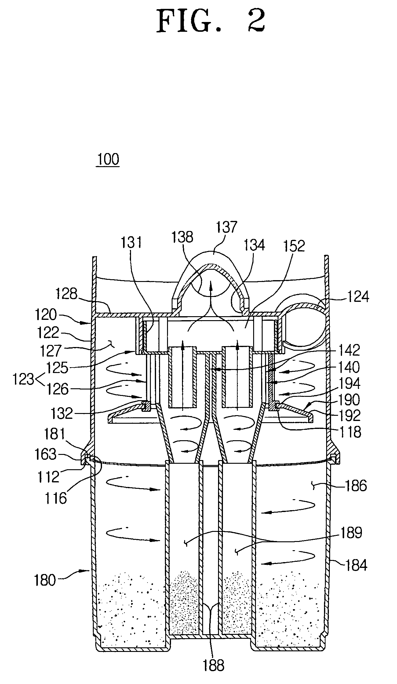
[0029]FIGS. 1 through 6 show a multi-cyclone dust separating apparatus according to a first exemplary embodiment of the present disclosure. Particularly, FIG. 1 is an appearance perspective view, FIG. 2 is a cross-sectional view taken along line II-II of FIG. 1, FIG. 3 is a partial perspective view of the multi-cyclone dust separating apparatus of FIG. 1 from which a first outer tub of a first cyclone unit is omitted, FIGS. 4 and 5 are partial cut-away perspective views exemplifying only a second cyclone unit of the multi-cyclone dust separating apparatus of FIG. 1, and FIG. 6 is a perspective view exemplifying a dust bin of the multi-cyclone dust separating apparatus of FIG. 1.

[0030]Referring to FIGS. 1 and 2, the multi-cyclone dust separating apparatus 100 apparatus according to...


PUM

PropertyMeasurementUnit
elasticaaaaaaaaaa
heightaaaaaaaaaa
forceaaaaaaaaaa

Abstract

The multi-cyclone dust separating apparatus includes a first cyclone unit including a first outer tub with a first air inlet and a cylindrical element with a first air outlet, and whirling air from the first air inlet to separate dust therefrom, the cylindrical element being disposed in the first outer tub to form a first cyclone chamber, along with the first outer tub; a second cyclone unit including a plurality of cyclones, each having a second air inlet for drawing in dust-laden air from the first cyclone chamber, to provide a second dust separation; and a dust bin including a first dust collecting chamber for collecting the dust separated by the first cyclone unit and a plurality of second dust collecting chambers for collecting the dust separated by the second cyclone unit.

Description

CROSS-REFERENCE TO RELATED APPLICATIONS[0001]This application claims the benefit under 35 U.S.C. §119 from U.S. Provisional Patent Application No. 61 / 001,887, filed Nov. 5, 2007, in the United States Patent and Trademark Office, and Korean Patent Application No. 10-2008-13556, filed on Feb. 14, 2008, in the Korean Intellectual Property Office, the entire disclosures of both of which are incorporated herein by reference.BACKGROUND OF THE INVENTION[0002]1. Field of the Invention[0003]The present disclosure relates to a dust separating apparatus, and, more particularly, to a multi-cyclone dust separating apparatus of a vacuum cleaner, which draws in air and separates dust or dirt from the air.[0004]2. Description of the Related Art[0005]In general, a dust collecting apparatus of a vacuum cleaner can be classified as either a dust collecting apparatus, which uses a filter, or a cyclone dust collecting apparatus, which separates dust from the air by centrifugal force. The term “dust” is ...

Claims


Application Information

Patent Timeline
Patent Type & Authority Patents(United States)
IPC IPC(8): B01D45/00
CPCA47L9/1625A47L9/1641B04C5/26B04C5/04B04C5/185A47L9/1691Y10S55/03A47L9/1683A47L9/10A47L9/16
Inventor OH, JANK-KEUNKIM, MIN-HA
Owner SAMSUNG GWANGJU ELECTRONICS CO LTD
Learn More