
Component array bracket assembly

Active Publication Date: 2010-06-22
ORACLE INT CORP
View PDF23 Cites 11 Cited by
  • Summary
  • Abstract
  • Description
  • Claims
  • Application Information

AI Technical Summary

Benefits of technology

[0011]Broadly speaking, the present invention fills these needs by providing a computer component positioning and securing bracket assembly for disk drives and other components arranged in one or more linear arrays within an array

Problems solved by technology

Efficient use of the space, while providing for necessary access and airflow, presents continuing challenges to the configuration and arrangement of disk drives, and other component devices within a system rack.
Such data re-build can take excessive amounts of time, which increases with the increasing numbers and capacity of component devices that can be accommodated on a single mid-plane spanning an array chassis due to smaller sizes of the component devices.

Method used


Image

  • Component array bracket assembly
  • Component array bracket assembly
  • Component array bracket assembly

Examples


Embodiment Construction

[0030]An invention for a bracket assembly and system for securing and arranging computer components in one or more linear arrays is described. In the following description, numerous specific details are set forth in order to provide a thorough understanding of the present invention. It will be understood, however, to one skilled in the art, that the present invention may be practiced without some or all of these specific details. In other instances, well known process operations have not been described in detail in order not to unnecessarily obscure the present invention.

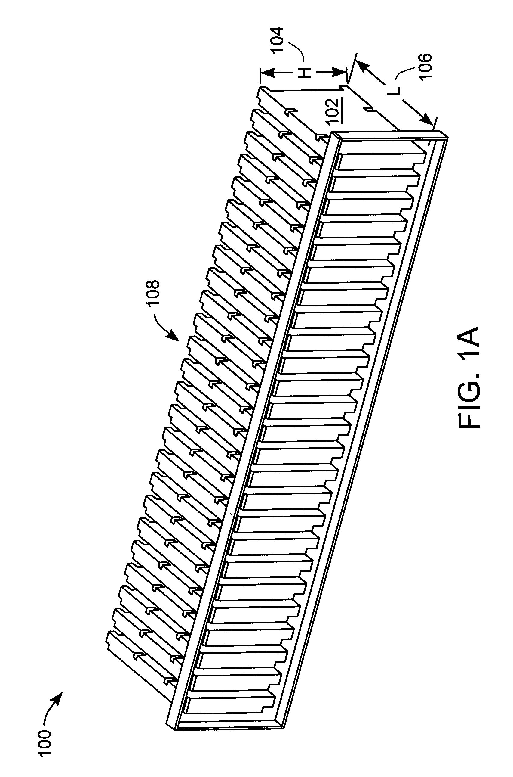
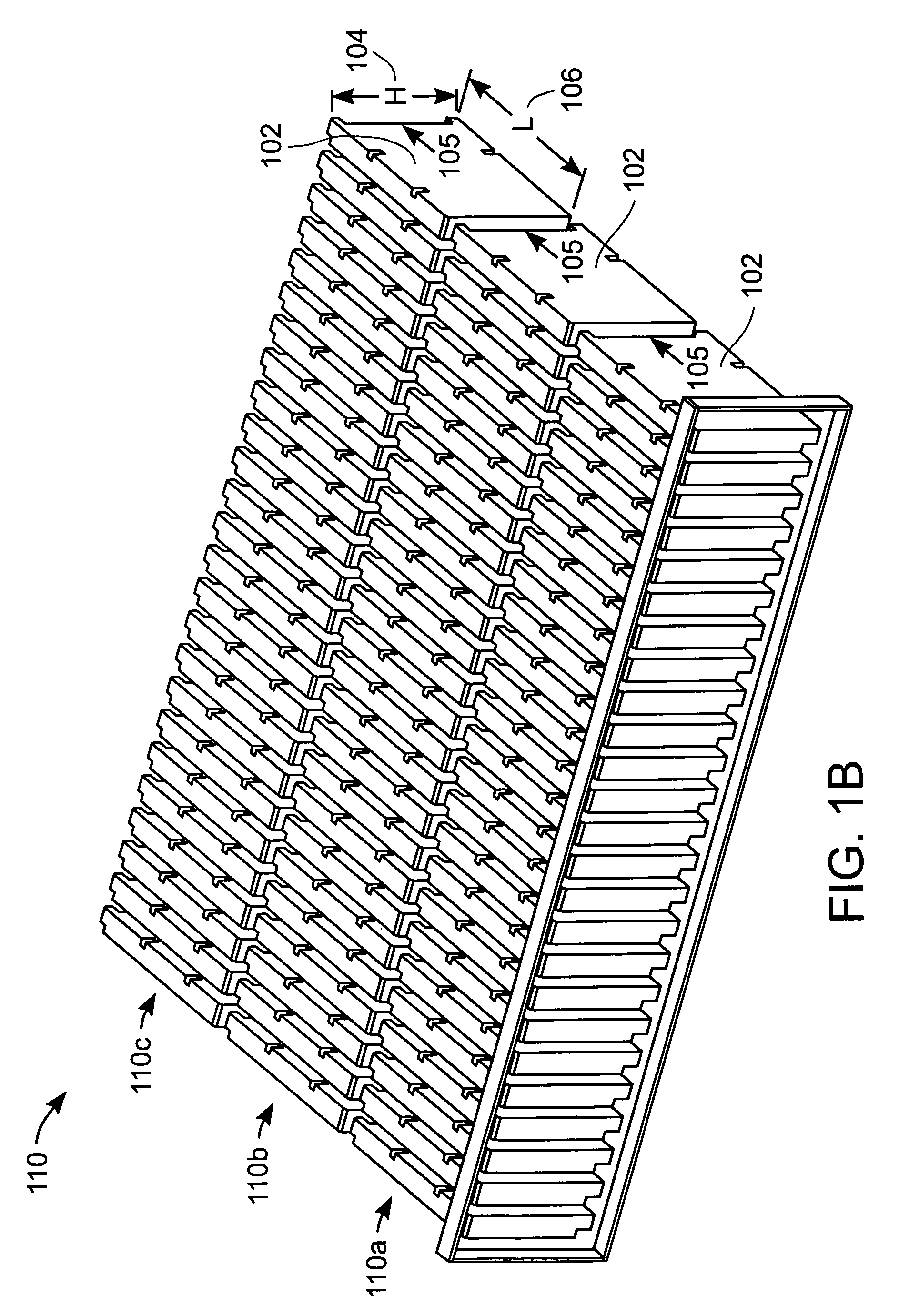
[0031]FIG. 1A is an array 100 of computer component devices 102 in a horizontally oriented component device 102 array. As used herein, “component devices,” or “network component devices” include network servers, routers, disk drive and other mass storage devices, tape back-up devices, and other similar related, generally computer components. Each component device 102 in FIG. 3A is oriented so that height “H”104 is l...


PUM


Abstract

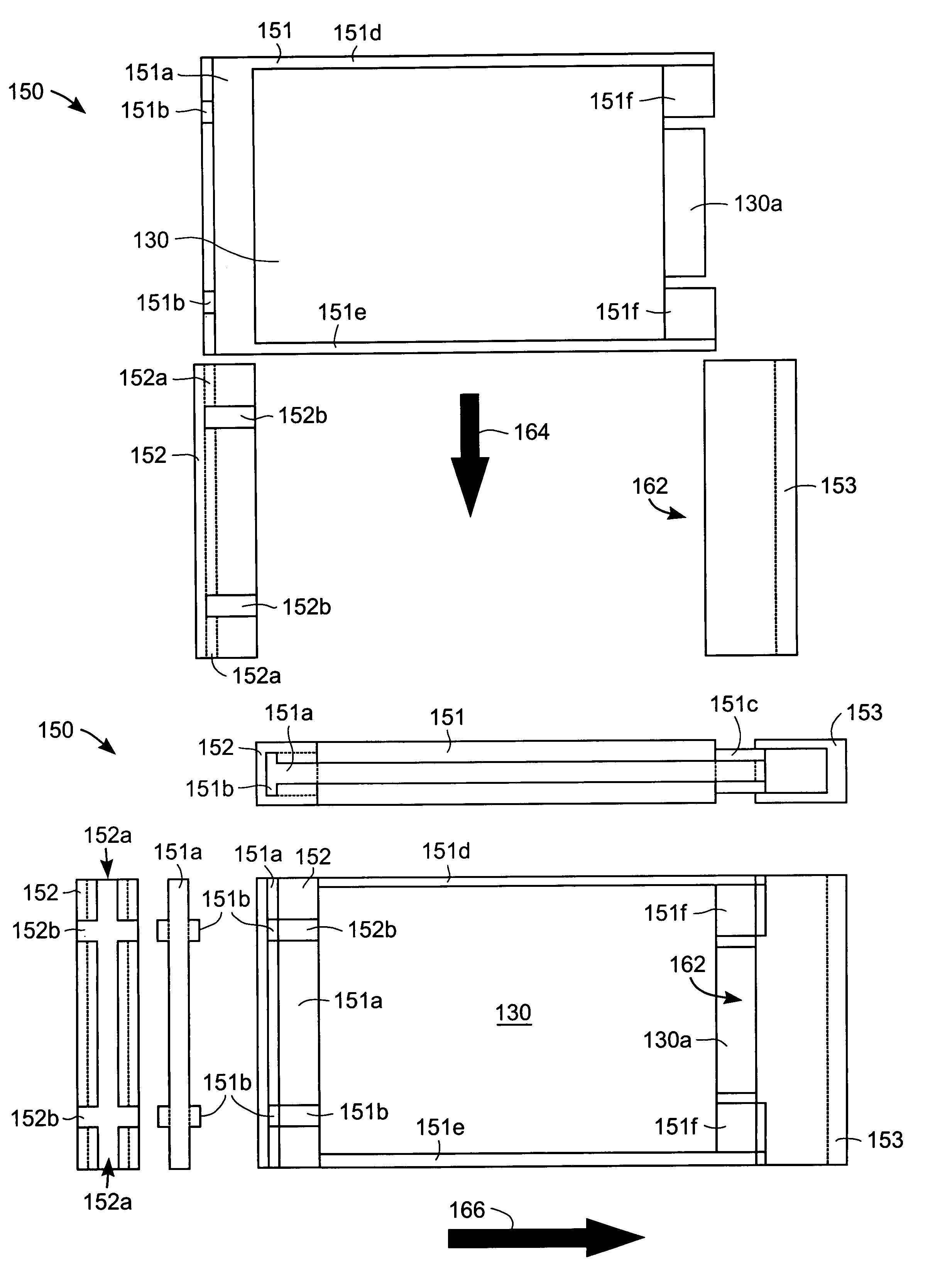
A component positioning and securing bracket assembly includes a front rail, a rear rail, and a bottom rail to define a front, a rear, and a bottom boundary of the component positioning and securing bracket assembly. The front rail, the rear rail, and the bottom rail define a structure into which is received the component in a first direction of movement, and a lever provides leveraged motion in a second direction of movement to connect a port of the component to a component connector and to secure the component in the component positioning and securing bracket assembly. The component positioning and securing bracket assembly is in an array of a plurality of components, in which any one component can be installed or removed without installing or removing any other component in the array.

Description

CROSS REFERENCE TO RELATED APPLICATION[0001]This application is related to U.S. patent application Ser. No. 10 / 800,121, filed on the same day as the instant application and entitled “DEVICE CARRIER SYSTEM.” This application is hereby incorporated by reference in its entirety for all purposes.BACKGROUND OF THE INVENTION[0002]1. Field of the Invention[0003]The present invention relates generally to computer network and network system components, and more specifically to a component device bracket assembly that provides for the component device to be installed into and removed from an array of component devices.[0004]2. Description of the Related Art[0005]Computer network server system and related components are typically housed in racks configured to house and to assimilate the functions of a plurality of component devices. System racks provide efficient organization for the plurality of components for ease of access, serviceability, expandability, power distribution, cooling, etc.[00...

Claims


Application Information

Patent Timeline
IPC IPC(8): H05K5/00A47B95/02G11B33/02B65D85/00
CPCH05K7/1489G11B33/127
Inventor CHONG, JR., FAY
Owner ORACLE INT CORP
Learn More