Eureka AIR delivers breakthrough ideas for toughest innovation challenges, trusted by R&D personnel around the world.

Motor control device

a technology of motor control and control device, which is applied in the direction of dynamo-electric converter control, dynamo-electric gear control, multiple dynamo-motor starters, etc., can solve the problems of becoming difficult to make the current detection value converge on the current command value, and it is difficult to appropriately perform current control

Inactive Publication Date: 2010-06-22
HONDA MOTOR CO LTD
View PDF14 Cites 3 Cited by
  • Summary
  • Abstract
  • Description
  • Claims
  • Application Information

AI Technical Summary

Benefits of technology

[0018]The motor may drive the vehicle, or may assist traveling of the vehicle which is driven by an internal combustion engine.
[0019]In this case, the occurrence of a relatively sudden change in the travelling behavior of the vehicle attributable to a phase change by the phase changing mechanism can be suppressed.

Problems solved by technology

Incidentally, in a motor according to the abovementioned conventional technology, in a case where current control is performed based on a torque command which is set for example corresponding to accelerator opening or the like related to the accelerator operation of the driver, so that a difference between a current command value and a current detection value with respect to the energizing current of the motor becomes zero, when the relative phase of the plurality of rotors is changed, there is the possibility that it becomes difficult to appropriately perform current control.
However, since this is an assumption, then when the induced voltage constant changes due to the change in the relative phases of the plurality of rotors, there is the possibility that it becomes difficult to make the current detection value converge on the current command value.

Method used


Image

  • Motor control device
  • Motor control device
  • Motor control device

Examples


Embodiment Construction

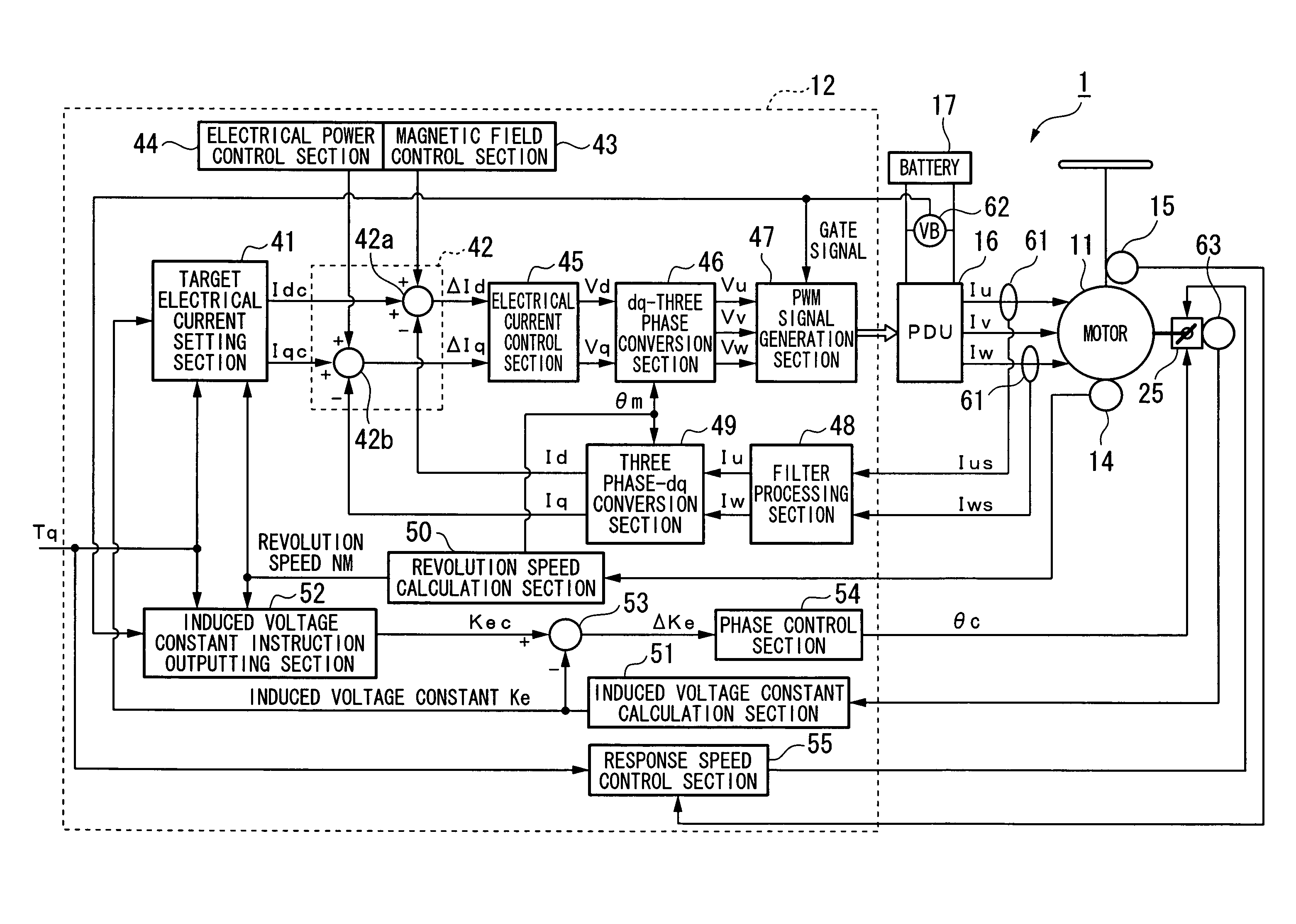
[0028]Hereunder, one embodiment of a motor control device of the present invention is described with reference to the appended drawings.

[0029]The motor control device 1 according to the present embodiment is installed in a vehicle, such as a hybrid vehicle or an electric vehicle, furnished with a motor as the propulsion source. More specifically, as shown in FIG. 1, a vehicle 10 is an electric vehicle furnished with a motor (Mot) 11 as the driving source, and the driving force of the motor 11 is transmitted to the front wheels Wf of the vehicle 10.

[0030]Moreover, when a driving force is transmitted to the motor 11 from the front wheels Wf side at the time of deceleration of the vehicle 10, the motor 11 functions as an electrical generator and generates a so called regenerative braking force, and the kinetic energy of the vehicle body is recovered as electrical energy (regenerative energy). Here for the vehicle 10 provided with a control apparatus 12, there is provided with various s...


PUM


Abstract

A motor control device includes: a motor that has a plurality of rotors which respectively have a magnetic piece, which drives or supplementarily drives a vehicle; a phase changing mechanism that changes relative phases of the plurality of rotors, and sets these to a predetermined induced voltage constant; and a speed control device that controls a phase changing speed of the phase changing mechanism.

Description

BACKGROUND OF THE INVENTION[0001]Priority is claimed on Japanese Patent Application No. 2006-236603, filed Aug. 31, 2006, the contents of which are incorporated herein by reference.[0002]1. Field of the Invention[0003]The present invention relates to a motor control device.[0004]2. Description of the Related Art[0005]Heretofore a motor equipped with a first permanent magnet piece and a second permanent magnet piece for which the phase positions are mutually changeable by means of, for example, servo pressure, so that the magnetic field flux can be changed, is known (for example refer to Japanese Unexamined Patent Application, First Publication No. S55-153300).[0006]Furthermore, heretofore for example in motors such as for hybrid vehicles, those provided with an adjustment mechanism in which a plurality of rotors, which are provided with magnetic poles with polarities that are serially different in the rotation direction, are arranged on the same rotation axis such that they are adja...

Claims


Application Information

Patent Timeline
Patent Type & Authority Patents(United States)
IPC IPC(8): H02P1/54H02P6/06H02P6/08H02P6/28H02P21/00H02P21/06H02P23/16H02P27/04H02P27/08
CPCB60L11/123B60L15/025H02P21/0035Y02T10/7258Y02T10/6217Y02T10/643Y02T10/7077H02P2207/03H02P21/22B60L50/61Y02T10/64Y02T10/62Y02T10/72Y02T10/70Y02T10/7072
Inventor FUJISHIRO, NAOKIATARASHI, HIROFUMIISEGAWA, HIROYUKI
Owner HONDA MOTOR CO LTD
Why Eureka
Eureka Blog
Learn More