Transceiver for full duplex communication systems

a communication system and transceiver technology, applied in the field of transceivers, can solve the problems of increasing the complexity and cost of the circuit, the noise level and harmonic distortion of the active elements within, and the inability to effectively reduce the echo effect of the transceiver b>100/b>, so as to reduce complexity, cost and power consumption, the effect of minimizing the parastatic capacitance

Active Publication Date: 2010-06-15
REALTEK SEMICON CORP
View PDF38 Cites 4 Cited by
  • Summary
  • Abstract
  • Description
  • Claims
  • Application Information

AI Technical Summary

Benefits of technology

[0011]According to certain embodiments, the parasitic capacitance effect is minimized and the echo cancellation performance is optimized. Furthermore, no unit gain buffers are required to drive next stages so that the complexity, the cost, and the power consumption are reduced. In addition, the noise and harmonic distortion of active elements are decreased and the signal quality is improved.

Problems solved by technology

However, an unavoidable parasitic capacitance effect in practical implementations is disregarded and therefore the echo effect of the transceiver 100 cannot be effectively reduced.
The transceiver of the prior art utilizes unit gain buffers to drive next stages and this results in increased complexity and cost of the circuit, and the noise level and harmonic distortion of the active elements within are raised.

Method used


Image

  • Transceiver for full duplex communication systems
  • Transceiver for full duplex communication systems
  • Transceiver for full duplex communication systems

Examples


first embodiment

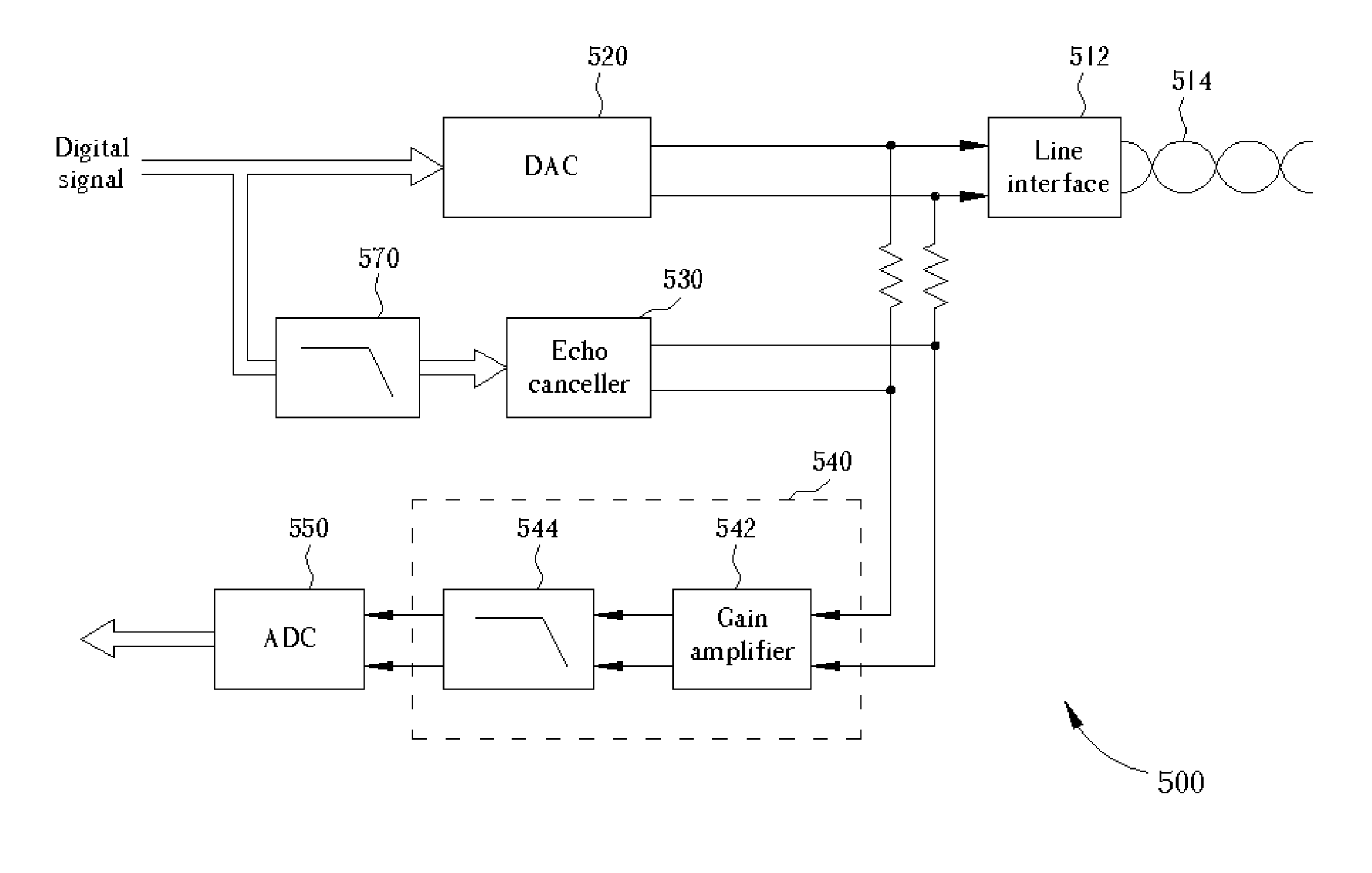
[0038]FIG. 5 depicts a schematic diagram of a transceiver 500 of a full duplex communication system according to the present invention. In the transceiver 500, the AFE circuit 540 comprises a gain amplifier 542 for adjusting the amplitude of the receive signal to increase the signal gain; and a filter 544 coupled to the gain amplifier 542 for filtering noises or harmonic components of the signal outputted from the gain amplifier 542 and for driving the next stage. Preferably, the gain amplifier 542 is a programmable gain amplifier (PGA) and the filter 544 is an OP-RC filter.

[0039]The block H(s) 570 shown in FIG. 6 is a low pass transfer function and can be implemented to satisfy formula (6) by either digital means or analog means. For example, a digital low pass filter can be employed to implement the block H(s). In another embodiment of the present invention, an RC network low pass filter is employed to implement the block H(s). A capacitor of the RC network low pass filter can be ...

second embodiment

[0047]FIG. 9 is a simplified schematic diagram of a transceiver 900 according to the present invention. A hybrid circuit of the transceiver 900 comprises a line driver 920 for transmitting a transmission signal to the channel via a matching resistor Rk; a cancellation signal generator 930 coupled to the line driver 920 for generating a cancellation signal according to the transmission signal; and a cancellation module 942 coupled to the line driver 920 and the cancellation signal generator 930 for eliminating the echo caused by the transmission signal.

[0048]The cancellation signal generator 930 of the present invention generates the cancellation signal according to the signal Vo′ outputted from the line driver 920. Then the cancellation signal is transmitted to the cancellation module 942.

[0049]FIG. 10 depicts an equivalent circuit diagram of the transceiver 900 of the present invention. Preferably, the cancellation signal generator 930 is a RC-network low pass filter having a resis...


PUM


Abstract

A transceiver in a full duplex communication system includes a hybrid circuit for transmitting a transmission signal or receiving a receive signal via the channel, the hybrid circuit includes an echo cancellation device for removing transmission signal components from the receive signal; wherein the hybrid circuit outputs a processed receive signal; and a gain amplifier being an OP-RC AGC is directly connected to the hybrid circuit for amplifying the processed receive signal, wherein a first node of the gain amplifier coupled to the echo cancellation device is a virtual ground.

Description

CROSS REFERENCE TO RELATED APPLICATIONS[0001]This is a continuation-in-part of U.S. application Ser. No. 10 / 709,935, filed Jun. 7, 2004, entitled “ECHO CANCELLATION DEVICE FOR FULL DUPLEX COMMUNICATION SYSTEMS”, which issued on Dec. 4, 2007, as U.S. Pat. No. 7,304,961, U.S. application Ser. No. 10 / 711,294, filed Sep. 8, 2004, entitled “ECHO CANCELLATION DEVICE FOR FULL DUPLEX COMMUNICATION SYSTEMS”, which issued on Dec. 11, 2007, as U.S. Pat. No. 7,307,965, U.S. application Ser. No. 10 / 904,338, filed Nov. 4, 2004, entitled “ECHO CANCELLATION DEVICE FOR FULL DUPLEX COMMUNICATION SYSTEMS”, which issued on Jun. 30, 2009, as U.S. Pat. No. 7,554,933, which are cooperated by reference herein.BACKGROUND OF INVENTION[0002]1. Field of the Invention[0003]The present invention relates to a transceiver, and more particularly, to a transceiver for a full duplex communication system.[0004]2. Description of the Prior Art[0005]As technology advances, network applications have become more and more p...

Claims


Application Information

Patent Timeline
Patent Type & Authority Patents(United States)
IPC IPC(8): H04L5/14
CPCH04L5/1461
Inventor CHIU, PAO-CHENGHUANG, CHEN-CHIH
Owner REALTEK SEMICON CORP
Why Eureka
Try Eureka