
Air conditioner

a technology for air conditioners and control boxes, which is applied in the field of air conditioners, can solve the problems of increasing the overall size troublesome for users, and difficulty in moving the air conditioner once installed, so as to achieve the effect of preventing damage to the electron components in the control box, maximizing the space efficiency of the air conditioner, and compact air conditioners

Active Publication Date: 2010-06-15
LG ELECTRONICS INC
View PDF15 Cites 1 Cited by
  • Summary
  • Abstract
  • Description
  • Claims
  • Application Information

AI Technical Summary

Benefits of technology

The present invention is an air conditioner that solves problems of existing air conditioners by maximizing space efficiency and improving the assembling capability of electronic components. The air conditioner includes a main drain pan, a base pan, an indoor blower unit, and a control box. The control box is installed vertically across the main drain pan and includes a box body and a box cover that can be bent. The control box support prevents the dropping of the control box and ensures safety during installation. The control box is designed to improve the assembling capability of the electronic components and reduces the manufacturing cost and short circuit. The technical effects of the present invention are improved space efficiency, improved assembling capability, improved safety, and reduced manufacturing cost.

Problems solved by technology

Since the conventional air conditioner, however, is large-sized or is generally installed on a wall of a building, it is difficult to move the air conditioner once installed.
This is troublesome for a user.
In the conventional movable air conditioner, a control box occupies a large space, increasing an overall size of the air conditioner.
Therefore, the electronic components may be damaged by the heat generated and accumulated in the control box.
Furthermore, since an inner space of the control box when the cover is opened is small, it is difficult to mount the electronic components in the control box and the assembling capability is deteriorated.

Method used


Image

  • Air conditioner
  • Air conditioner
  • Air conditioner

Examples


Embodiment Construction

[0042]Reference will now be made in detail to the preferred embodiments of the present invention, examples of which are illustrated in the accompanying drawings. The invention may, however, be embodied in many different forms and should not be construed as being limited to the embodiments set forth herein; rather, these embodiments are provided so that this disclosure will be thorough and complete, and will fully convey the concept of the invention to those skilled in the art.

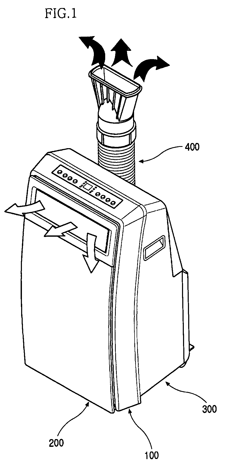
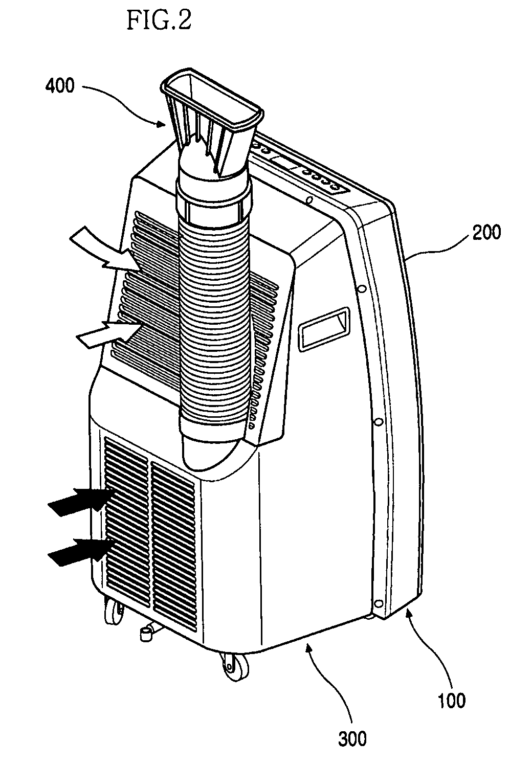
[0043]FIGS. 1 and 2 are respective front and rear perspective views of an air conditioner according to an embodiment of the present invention.

[0044]Referring to FIGS. 1 and 2, an air condition according to an embodiment of the present invention includes a front frame 100 defining an outer appearance of a front half of the air conditioner and a rear frame defining a rear appearance of a rear half of the rear frame 300.

[0045]The front frame 100 forms a frame of the front half of the air conditioner and forms part...


PUM


Abstract

There is provided an air conditioner. The air conditioner includes a main drain pan dividing an inner space of the air conditioner into upper and lower halves, a base pan defining a lower outer appearance of the air conditioner, an indoor blower unit that is installed on an upper portion of the main drain pan to guide introduction and discharge of indoor air, and a control box in which a plurality of electronic components controlling the operation of the air conditioner are installed. The control box is installed vertically across the main drain pan.

Description

[0001]This application claims the benefit of Korean Patent Application Nos. 10-2006-0061888 filed on Jul. 3, 2006 and 10-2006-0109176 filed on Nov. 6, 2006, which are hereby incorporated by reference for all purposes as if fully set forth herein.BACKGROUND OF THE INVENTION[0002]1. Field of the Invention[0003]The present invention relates to an air conditioner and, more particularly, an air conditioner in which a control box in which electronic components are installed are installed in a vertical direction and fixed to a main drain pan and an indoor blower unit.[0004]2. Description of the Related Art[0005]Generally, an air conditioner includes a compressor, an expansion valve, and an indoor heat exchanger. The air conditioner uniformly maintains a room temperature to provide an enjoyable atmosphere to human beings.[0006]That is, the air conditioner is a heating / cooling device installed at an indoor space of a room, office, or home to heat or cool the indoor space. The air conditioner...

Claims


Application Information

Patent Timeline
Patent Type & Authority Patents(United States)
IPC IPC(8): F25D21/14F24F1/02
CPCF24F1/025F24F13/222F24F13/20F24F2013/207F24F1/022F24F1/04
Inventor LEE, JONG HOKIM, MOON SHIN
Owner LG ELECTRONICS INC
Learn More