
Method for manufacturing a dental prosthesis and an appliance for implantation thereof

Inactive Publication Date: 2010-06-08
DE MOYER PHILIPPE ALBERT PAUL GHISLAIN
View PDF9 Cites 27 Cited by
  • Summary
  • Abstract
  • Description
  • Claims
  • Application Information

AI Technical Summary

Benefits of technology

[0011]The aim of the present invention is to develop a method of manufacturing a dental prosthesis to be implanted in the jaw of the patient that overcomes the aforementioned drawbacks and that makes it possible to simplify the positioning of these prostheses, whilst obtaining increased precision and reliability.
[0023]This method offers the great advantage of determining by image the position of each of the implants to be implanted in an ideal position in the jaw, according to the situation of the mandibular nerves, sinuses, etc. Through the appropriate guidance of the invention, it is possible in a reproducible manner to introduce into a pattern and subsequently in the same way into the jaw an implant analogue and respectively a similar implant. This introduction is always carried out so that the implant and the implant analogue are fixed in their support brackets (pattern or jaw) with the position determined on the images in two and three dimensions, this is to say with the same axial orientation and at the same depth. In addition, by an appropriate marking, it is possible, according to the invention, for the head of the implant and that of the implant analogue, which generally have the shape of a prism with a triangular or polygonal cross section and on which the prosthesis is then placed, to be situated in rotation in a precise position, which will be the same in both cases. This offers the exceptional advantage of being able to produce the unitary or multiple definitive prosthesis on a pattern, even before the placing of the implants, and to place this prosthesis on the implants, on the day when these are placed in position.
[0030]This method makes it possible to make an image of a radiological guide provided with individual artificial teeth, very close to what will be necessary for the prosthesis. Advantageously, these artificial teeth consist of a material visible in radiological imaging, which, preferably, is a mixture of resin normally used for fashioning artificial teeth and barium sulphate. This is introduced into the mixture for example in a proportion of about 30% by volume.

Problems solved by technology

1. Freehand with a wide cut in the gum and detachment of the latter. Fitting takes place in an archaic manner without any reference or guiding mark with respect to the future prosthesis. Although this technique is the worst and gives results that are often aesthetically, functionally and hygienically disastrous, it is the most widely used. It is also the one that causes the most accidents (rupture of the mandibular nerve, piercing of the sinus, rupture of the cortices, etc).
2. Freehand with a wide cut in the gum and a detachment of the latter, the positioning takes place in a more or less precise manner since the dental laboratory has produced a surgical guide that more or less prefigures the future prosthesis. This technique is the second most widely used but the drawback is that the surgical guide is often unusable because of the cutting of the gum, which prevents the fitting thereof. With this technique there are also often poor results at an aesthetic, functional or hygienic level and accidents as aforementioned are numerous.
3. With the hand guided by drilling guides produced from a computerised plan. This technique makes it possible to place drilling cylinders in these guides at precise points according to the bone or according to the bone and the future prosthesis. Two distinct technologies apply this technique:Guides are produced from steriolithographic models, that is to say on the basis of images issuing from dental scanning. Artefacts often interfere with the production of these guides not always making it possible to use them through lack of precision.Guides are produced from an impression and a radiological guide that is produced on the basis of this impression in silicone (rather than on the basis of an image issuing from dental scanning). This radiological guide is then converted into a surgical guide by the insertion of guide cylinders for the drilling and the positioning of implants in the jaw.
However, it does not prevent all damage to the patient since the drilling is still manual and skidding remains possible.
This technique is expensive and is the least used.
All these techniques together have the drawback of having to produce the final prosthesis after taking an impression of the jaw where the implants were placed previously, which is carried out several weeks after the positioning of the implants, which is complex and requires many post-operative interventions, which are difficult for the patient.

Method used


Image

  • Method for manufacturing a dental prosthesis and an appliance for implantation thereof
  • Method for manufacturing a dental prosthesis and an appliance for implantation thereof
  • Method for manufacturing a dental prosthesis and an appliance for implantation thereof

Examples


Embodiment Construction

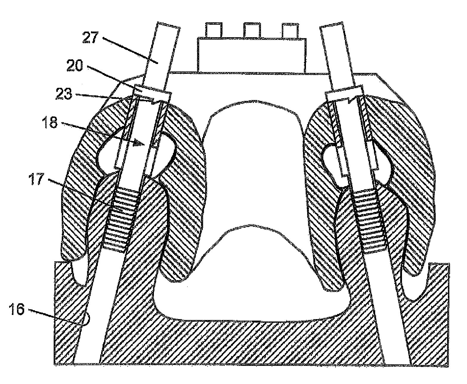
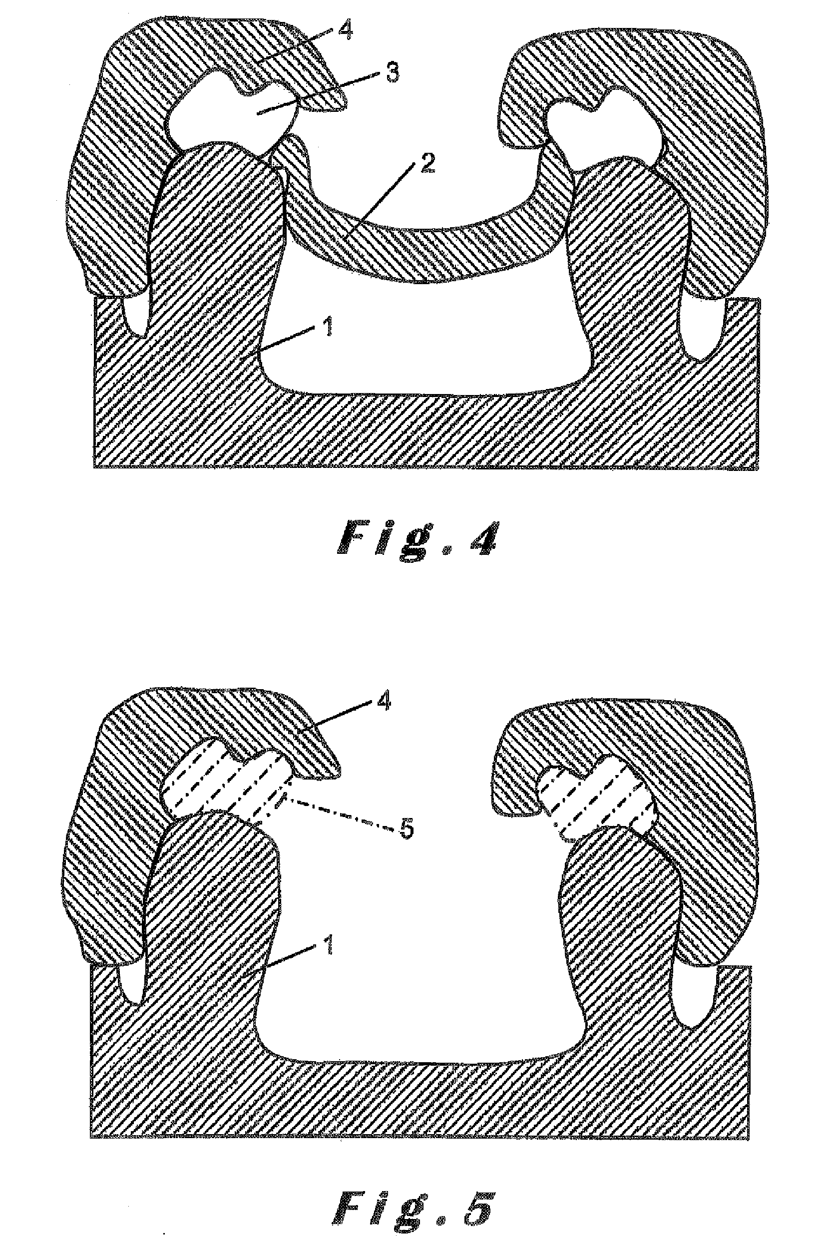
[0055]In the various drawings, the identical or similar elements bear the same references.

Production of a Radiological Guide

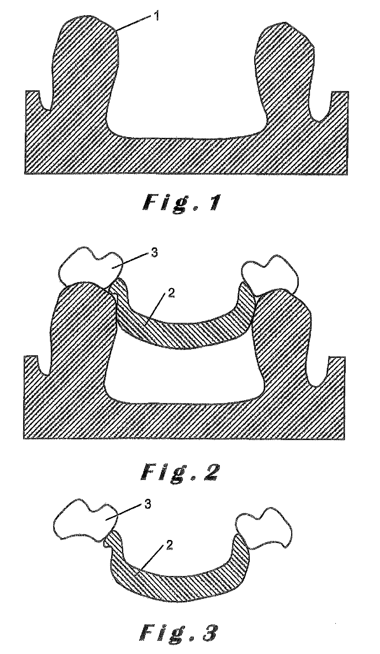
[0056]First of all a precise and non-compressive impression of the jaw of the patient is produced in silicone with moderate or low viscosity in order to obtain a three-dimensional mould of the gum and teeth. The same procedure is followed to obtain an impression of the antagonist of the jaw to be treated and thus a mould of this antagonist. From these impressions patterns made from hard plaster are cast, preferably three times for the pattern 1 of the jaw to be treated (see FIG. 1) and once for the antagonist jaw.

[0057]As is clear from FIG. 2, there is then produced on the pattern 1 a precise mounting (“wax-up”) by means of a mounting base 2 made from wax or resin and selected false teeth 3, which can be found on the market, for example under the trade name Physiodens. This mounting must prefigure with precision the prosthetic result and must therefore be tried...


PUM


Abstract

A method of manufacturing a dental prosthesis to be implanted in a jaw of a patient, including the production of a radiological guide whose image, when the guide is placed in position on the jaw of the patient, can be processed for introducing virtual implants and guide cylinders in a surgically appropriate position; drilling holes into the guide on the basis of information obtained from the processing and placing real guide cylinders into the holes in order to form a surgical guide; placing the surgical guide on a pattern of the patient's jaw and drilling holes into the pattern through the guide cylinders; placing implant analogues into the holes drilled into the pattern; and producing the dental prosthesis on the pattern. Also, an appliance for carrying out the manufacturing method.

Description

BACKGROUND OF THE INVENTION[0001]The present invention relates to a method of manufacturing a dental prosthesis to be implanted in a jaw of a patient and an appliance used for such an implantation.[0002]Implants are at the moment positioned in four ways:[0003]1. Freehand with a wide cut in the gum and detachment of the latter. Fitting takes place in an archaic manner without any reference or guiding mark with respect to the future prosthesis. Although this technique is the worst and gives results that are often aesthetically, functionally and hygienically disastrous, it is the most widely used. It is also the one that causes the most accidents (rupture of the mandibular nerve, piercing of the sinus, rupture of the cortices, etc).[0004]2. Freehand with a wide cut in the gum and a detachment of the latter, the positioning takes place in a more or less precise manner since the dental laboratory has produced a surgical guide that more or less prefigures the future prosthesis. This techn...

Claims


Application Information

Patent Timeline
IPC IPC(8): A61C19/04
CPCA61C1/084A61C8/0089A61C2201/005A61C13/00A61C1/08A61C8/00
Inventor DE MOYER, PHILIPPE ALBERT PAUL GHISLAIN
Owner DE MOYER PHILIPPE ALBERT PAUL GHISLAIN
Learn More