DC-motor

a dc-motor and motor shaft technology, applied in the field of dc-motors, can solve the problems of deterioration of the large axial dimension of the dc-motor, electrical wear, etc., and achieve the effect of improving the wear resistance of the brush and good control response of the dc-motor

Inactive Publication Date: 2010-06-01
MITSUBISHI ELECTRIC CORP
View PDF23 Cites 7 Cited by
  • Summary
  • Abstract
  • Description
  • Claims
  • Application Information

AI Technical Summary

Benefits of technology

[0016]The present invention is made to solve the problem described above, and aims to enlarge contact areas of the first brushes without making larger the external diameter of the disk on which the commutator is provided. That is, this invention aims to obtain a DC-motor in which the wear resistance of the first brushes can be enhanced while maintaining a good control-response, so that its axial direction can drastically be shortened, resulting in enabling its downsizing.
[0018]The DC-motor according to the present invention can not only enhance wear resistance of the brushes while maintaining a good control-response of the DC-motor, but also be downsized.

Problems solved by technology

The bigger the diameter of the disk becomes, the more increased the moment of inertia thereof and the sliding-frictional resistance working between the commutator and the first brushes are; therefore, there has been a problem in that the control-response of the DC-motor is deteriorated.
However, in an actual first-type DC-motor, because the first brushes are in contact with the commutator, electrical polarities at the tips of the first brushes change frequently, resulting in their electrical wear; therefore, the first brushes are used that have an overall length longer than that of the second brushes.
That is, the first brushes, having an overall length longer than that of the second brushes, are axially in contact with the commutator, resulting in a large axial dimension of the DC-motor; therefore, a problem has been that the DC-motor can not be downsized.

Method used


Image

  • DC-motor
  • DC-motor
  • DC-motor

Examples


embodiment 1

[0034]An embodiment according to the present invention will be explained below, based on the views.

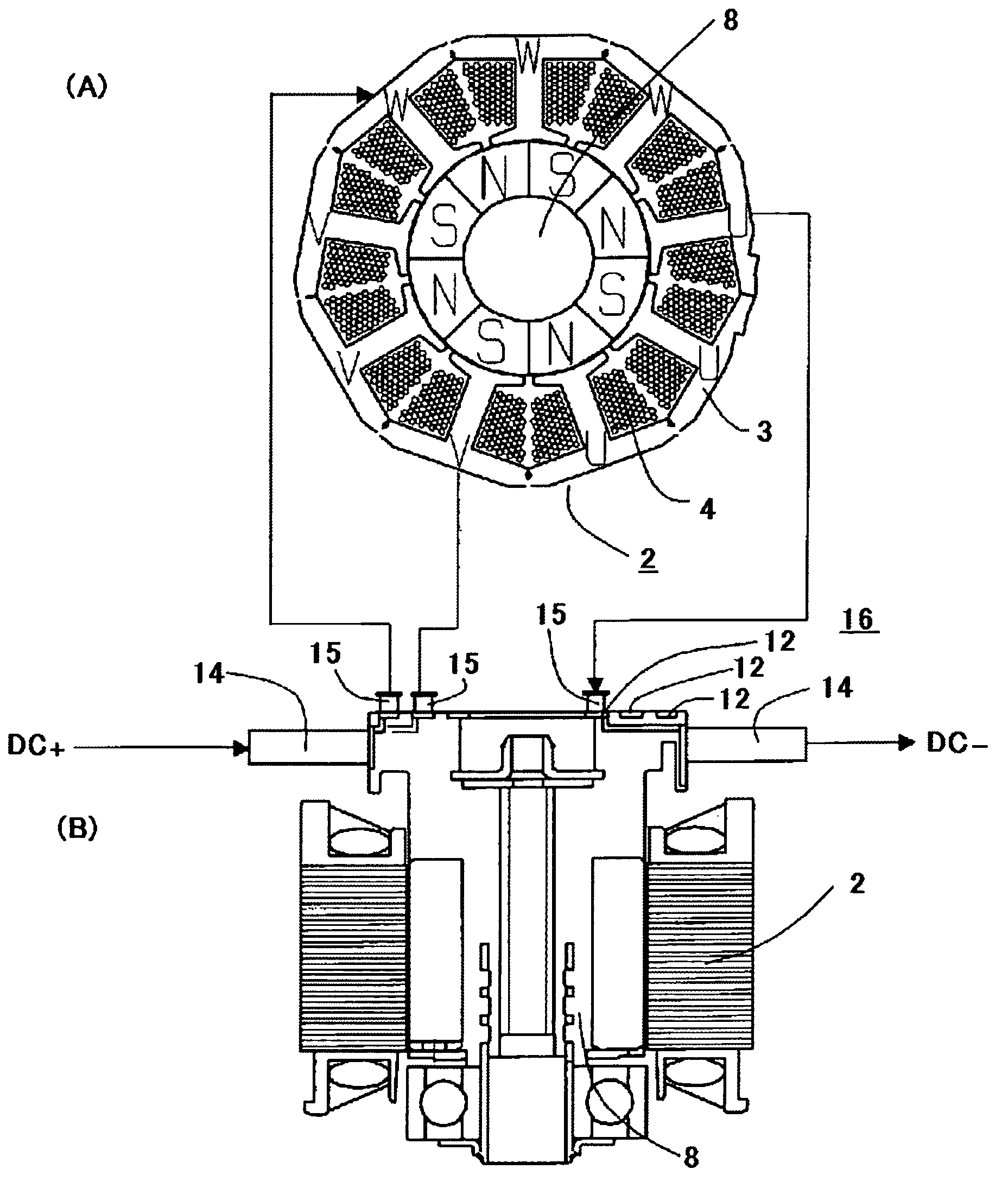
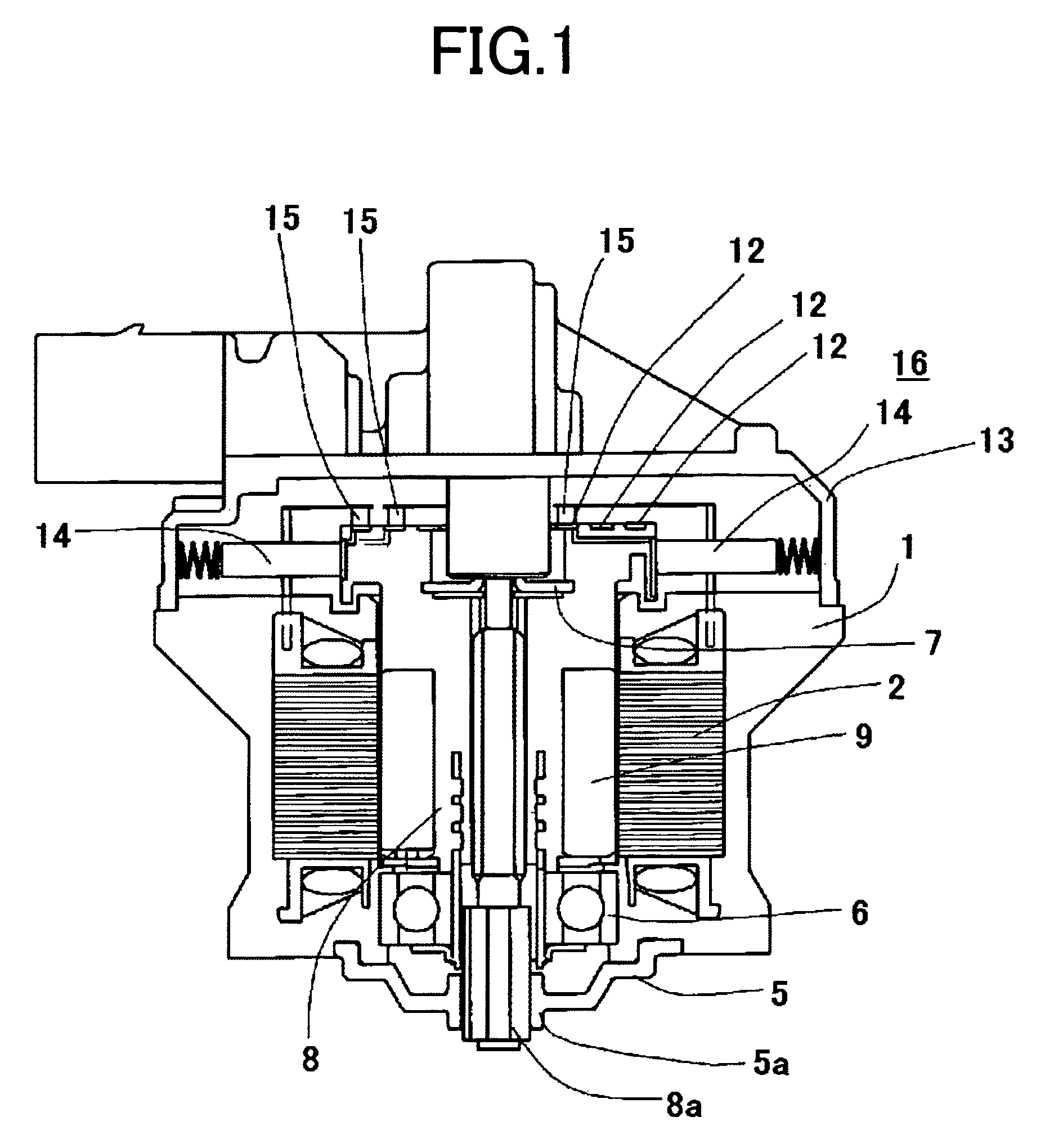
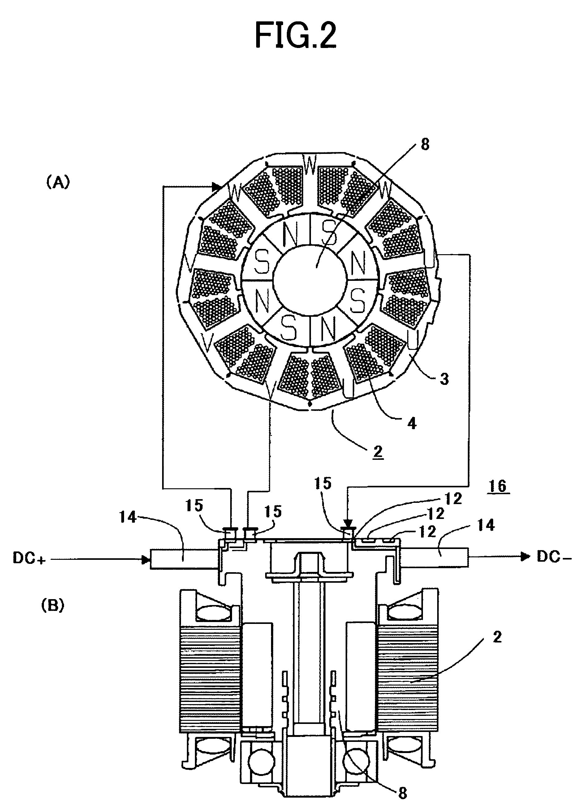
[0035]FIG. 1 is a sectional view illustrating a configuration of a DC-motor of Embodiment 1 according to the present invention. FIG. 2 illustrate current flows in a current-carrying unit of the DC-motor shown in FIG. 1, and FIG. 2(A) is a top view thereof and FIG. 2(B) is a side view thereof. FIG. 3 is a perspective view illustrating configurations of a commutator and slip rings shown in FIG. 1. FIG. 4 are top views for explaining a method of manufacturing a stator shown in FIG. 1.

[0036]In FIG. 1, numeral 1 represents a motor case formed of resin material, and numeral 2 represents a stator resin-molded integrally with the motor case 1. As shown in FIG. 4(A), magnetic-pole teeth 3a are each formed on core pieces 3b to protrude therefrom. A stator core 3 is formed by laminating a predetermined number of magnetic-material plates each of which includes the core pieces 3b connected through ...


PUM


Abstract

In a DC-motor according to the present invention, contact areas of first brushes can be enlarged without enlarging the external diameter of a disk on which a commutator is provided; therefore, the wear resistance of the first brushes can be enhanced while maintaining a good control-response; and at the same time, the axial dimension can be shortened dramatically, so that the DC-motor can be downsized. The first brushes 14 are radially in contact with the commutator 11, and second brushes 15 are axially in contact with slip rings 12 that are formed circumferentially inside the commutator 11.

Description

BACKGROUND OF THE INVENTION[0001]1. Field of the Invention[0002]The present invention relates to a DC-motor in which a DC current supplied from a power supply is commutated by a commutator and is supplied through slip rings into magnetizing coils.[0003]2. Description of the Related Art[0004]Generally, the commutator of a DC-motor is split into multiple segments so as to commutate a current supplied through first brushes from a power supply.[0005]A first type of conventional DC-motors is configured in such a manner that the first brushes are axially in contact with the commutator while second brushes are axially in contact with slip rings that are split into three pieces and circumferentially formed outside the commutator (for example, refer to Patent Document 1).[0006]A second type of conventional DC-motors is configured in such a manner that the first brushes are radially in contact with the commutator while the second brushes are radially in contact with slip rings that are split ...

Claims


Application Information

Patent Timeline
Patent Type & Authority Patents(United States)
IPC IPC(8): H02K11/00
CPCH02K23/62H02K13/003H02K13/006
Inventor YOKOYAMA, MASAYUKIFUJITA, YOUICHIMIYOSHI, SOTSUOOKETANI, NAOHIRO
Owner MITSUBISHI ELECTRIC CORP
Why Eureka
Try Eureka