Conveyor belt scraper

a scraper and conveyor belt technology, applied in the direction of conveyor parts, cleaning, transportation and packaging, etc., can solve the problems of large heat generation the frictional contact between the scraper and the belt is not easy to solve, etc., to reduce the build-up of heat in the assembly and reduce the impact

Inactive Publication Date: 2010-06-01
MAT
View PDF9 Cites 2 Cited by
  • Summary
  • Abstract
  • Description
  • Claims
  • Application Information

AI Technical Summary

Benefits of technology

[0010]With this feature heat generated in the blade segment and bracket can advantageously be transmitted through the boss to the linkage, thereby limiting the build up of heat in the assembly.
[0011]In the preferred embodiment, the scraper also includes a relatively flexible curtain extending over the linkage, the boss extending through an aperture in the curtain. With this configuration, the curtain protects the linkage from falling material scraped from the conveyor belt, but still allows direct heat transmission to take place from the bracket to the boss and hence to the linkage itself.
[0012]The preferred embodiment also includes a relatively stiff plastics deflector extending downwardly, over the upstream side of the curtain, from the blade segment. Advantageously, the bracket supports the blade segment and deflector in such a position that the deflector has a substantially vertical orientation at initial installation and throughout subsequent movement relative to the belt as the blade segment wears. With this feature, falling material scraped from the belt will apply less impact and wear to the deflector which is accordingly better able to protect the curtain, which in turn is then able better to protect the linkage itself from that falling material.

Problems solved by technology

Problems have however been encountered in situations where the conveyor belt runs “dry”, i.e. there is no conveyed material on the belt.
Frictional contact between the scraper and the belt generates substantial heat.
However when the belt runs “dry”, there is no such removal of heat and excessive heat can build up in the assembly, possibly leading to heat deterioration of the curtain and deformation or even melting of the plastics deflector.
This in turn can lead to a loosening of the connection between the bracket and the linkage.
The loosened bracket, i.e. blade segment, can then vibrate or chatter against the belt, resulting in further build-up of heat and rapid wear to the blade and also to the other mechanical components.
Rapid wear of the scraper apparatus can also take place in situations where particularly abrasive particulate material is transported by the conveyor belt.
It has been observed that the deflector itself can undergo rapid wear as a result of the material falling onto it.
It is believed that such wear is mainly attributable to the fact that the deflector is oriented at a relatively acute angle relative to the horizontal and so is largely exposed to vertically falling material which rapidly abrades it.
If the deflector and curtain are worn through, the mechanical linkage itself will be exposed directly to the falling material scraped off the belt, and this may have the effect of shortening the life of the scraper.

Method used


Image

  • Conveyor belt scraper
  • Conveyor belt scraper
  • Conveyor belt scraper

Examples


Embodiment Construction

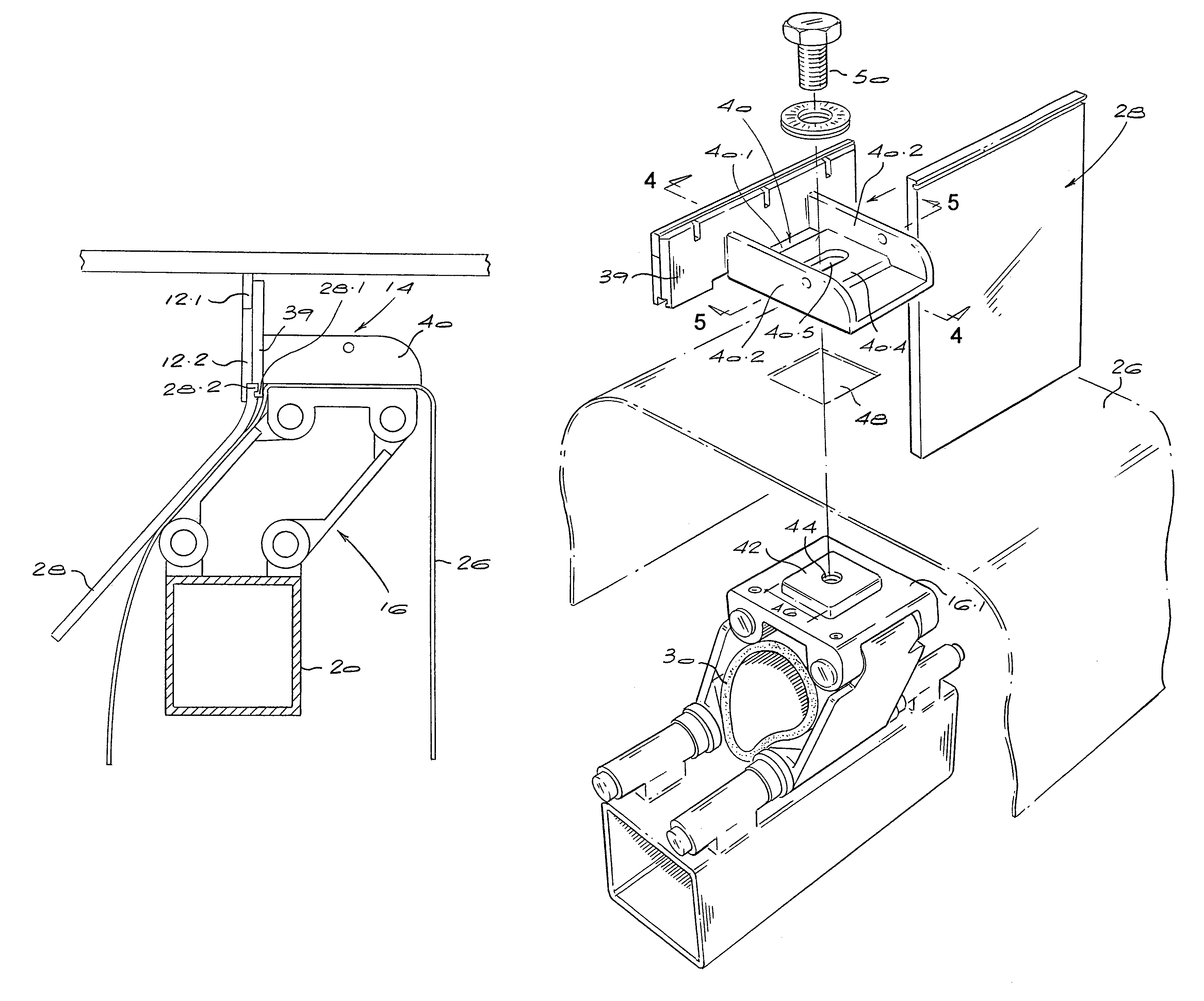
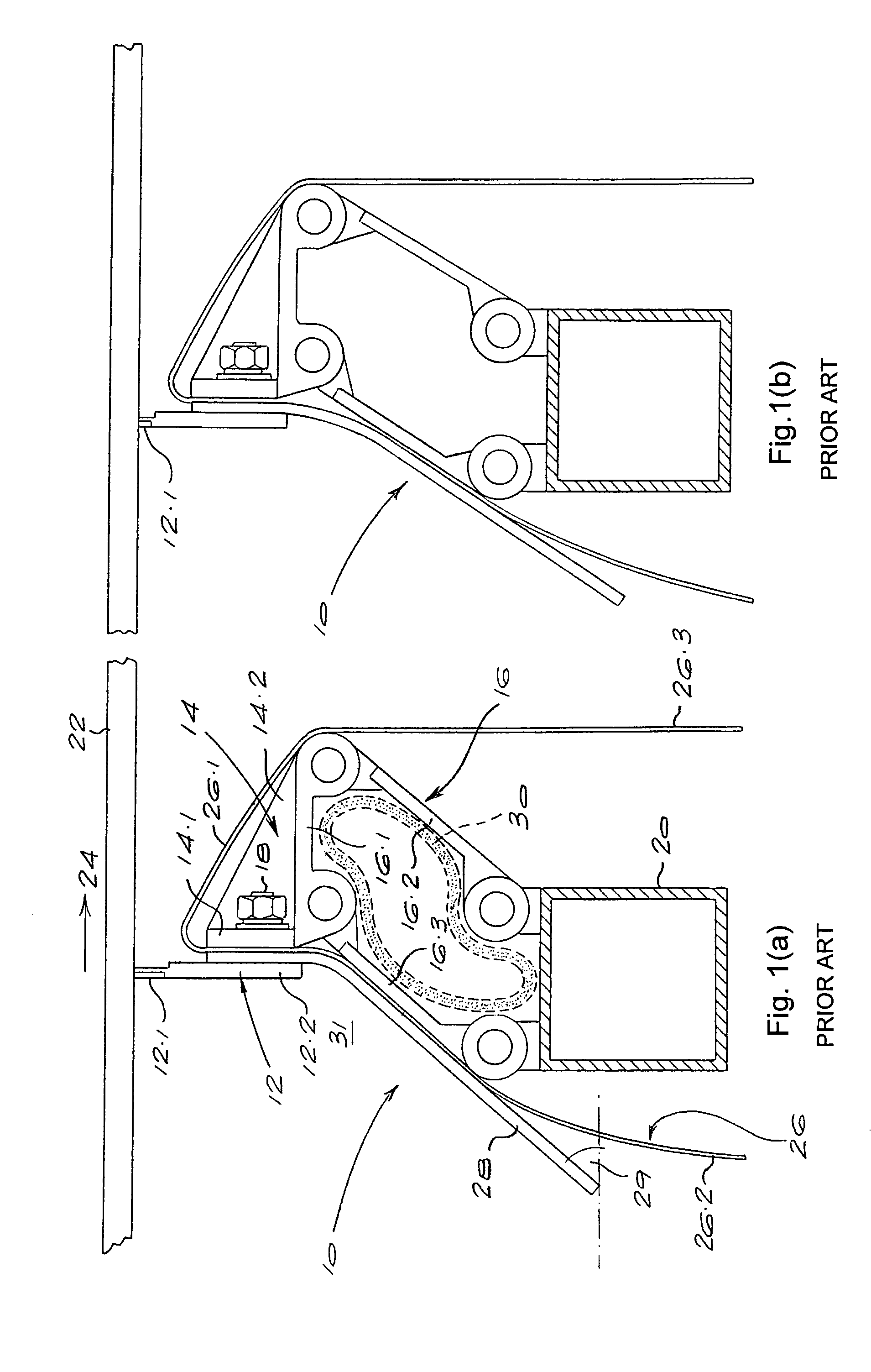
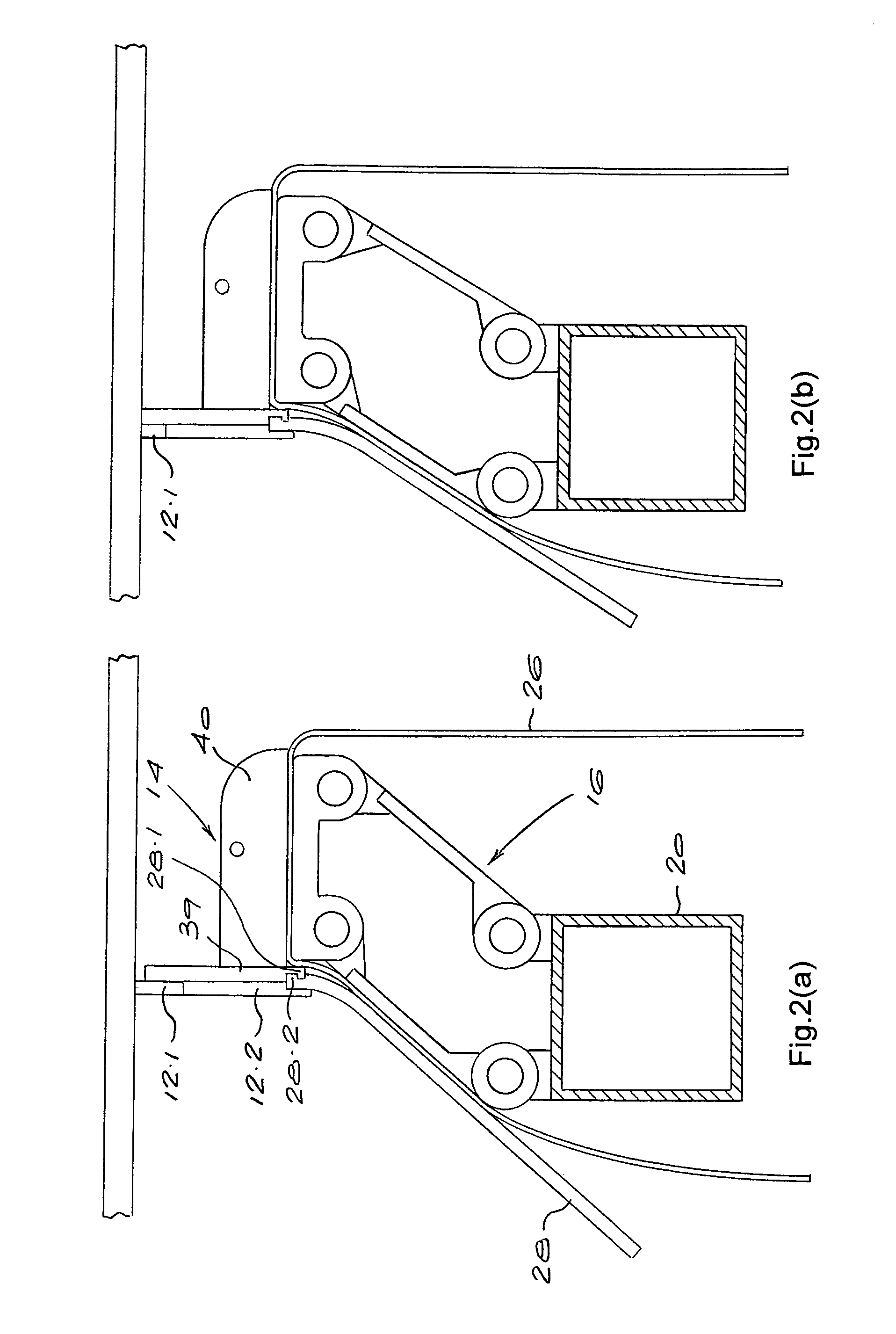
[0032]FIGS. 1(a) and 1(b) illustrate components of a conventional conveyor belt scraper of the type sold under the trade mark DIRTWHACKER®. The scraper 10 includes a blade segment 12 supported by a steel blade segment support bracket 14. The blade segment 12 consists of an insert 12.1 of tungsten carbide or other suitably hard material mounted in a rebate in a steel plate 12.2.

[0033]The scraper 10 also includes a parallelogram linkage 16 including hingedly connected steel links 16.1, 16.2 and 16.3. The bracket 14 is formed as an integral part of the upper link 16.1 and includes an upright steel plate 14.1 reinforced by gussets 14.2. The plate 12.2 is bolted to the plate 14.1 by bolts 18. The links 16.2 and 16.3 of the linkage 16 are hinged to a steel support bar 20 which forms part of the linkage and also forms part of the support structure for the scraper 10. Together with the bracket 14, the linkage 16 forms a blade segment support.

[0034]The numeral 22 indicates the bottom run of ...


PUM


Abstract

The invention concerns a conveyor belt scraper (10) which includes blade segments (12) each arranged to scrape a portion of the width of a conveyor belt (22). Each blade segment is supported by a bracket (14) which is mounted to a link (16.1) of a deformable, parallelogram linkage (16). An inflatable hose (30) extends through and acts on the linkages to urge the blade segments against the conveyor belt. The link has a projecting, holed boss (42) and the bracket has a recess (40.3) to receive the boss with the hole of the boss aligned with a hole in the base of the recess to receive a fastener (50) that connects the bracket to the linkage in thermally transmitting relationship. This relationship reduces heat degradation of components of the scraper.

Description

BACKGROUND TO THE INVENTION[0001]This invention relates to a conveyor belt scraper.[0002]U.S. Pat. No. 6,076,656 describes a conveyor belt scraper which includes a segmented scraper blade composed of blade segments arranged side by side on blade segment supports each of which includes a parallelogram linkage. A gas inflated biasing means, typically an inflatable tube or hose, extends through the linkages and is inflated to cause the linkages to displace the blade segments towards the belt surface. The individual mounting of the blade segments enables them to wear at different rates, to take account of different belt loading conditions across the width of the belt, while still maintaining an effective scraping action.[0003]Conveyor belt scrapers according to U.S. Pat. No. 6,076,656 are marketed under the trade marks DIRTWHACKER® and SCAVENGER®. These scrapers include, for each parallelogram linkage, a flexible curtain which hangs over the linkage and prevents material which is scrape...

Claims


Application Information

Patent Timeline
Patent Type & Authority Patents(United States)
IPC IPC(8): B65G45/16B65G45/12
CPCB65G45/16
Inventor MAT
Owner MAT
Why Eureka
Try Eureka