
Method to reduce acoustic coupling in audio conferencing systems

a technology of audio conferencing and coupling, applied in the field of audio conferencing systems, can solve the problems of reducing the performance of loudspeaker-to-beam coupling when required, full-duplex conferencing system, etc., and achieves enhanced full-duplex operation, reduced loudspeaker feedback, and enhanced near-end speech quality.

Active Publication Date: 2010-05-25
MITEL
View PDF8 Cites 36 Cited by
  • Summary
  • Abstract
  • Description
  • Claims
  • Application Information

AI Technical Summary

Benefits of technology

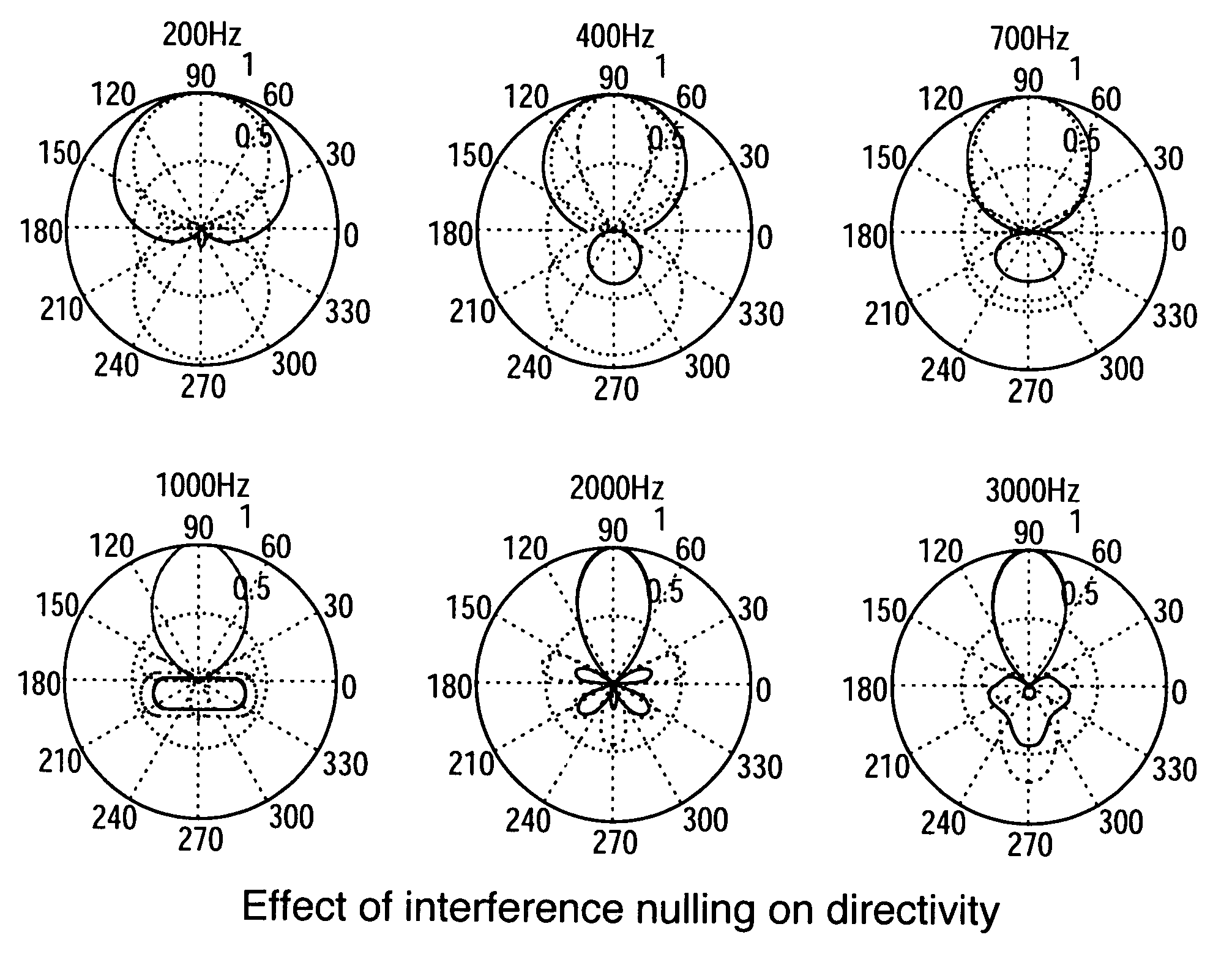
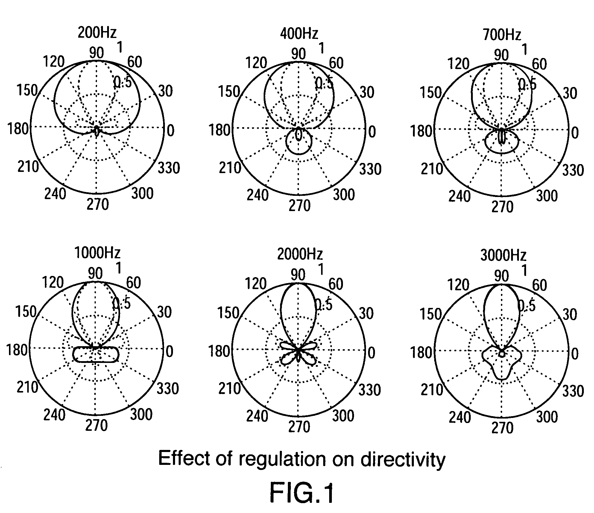
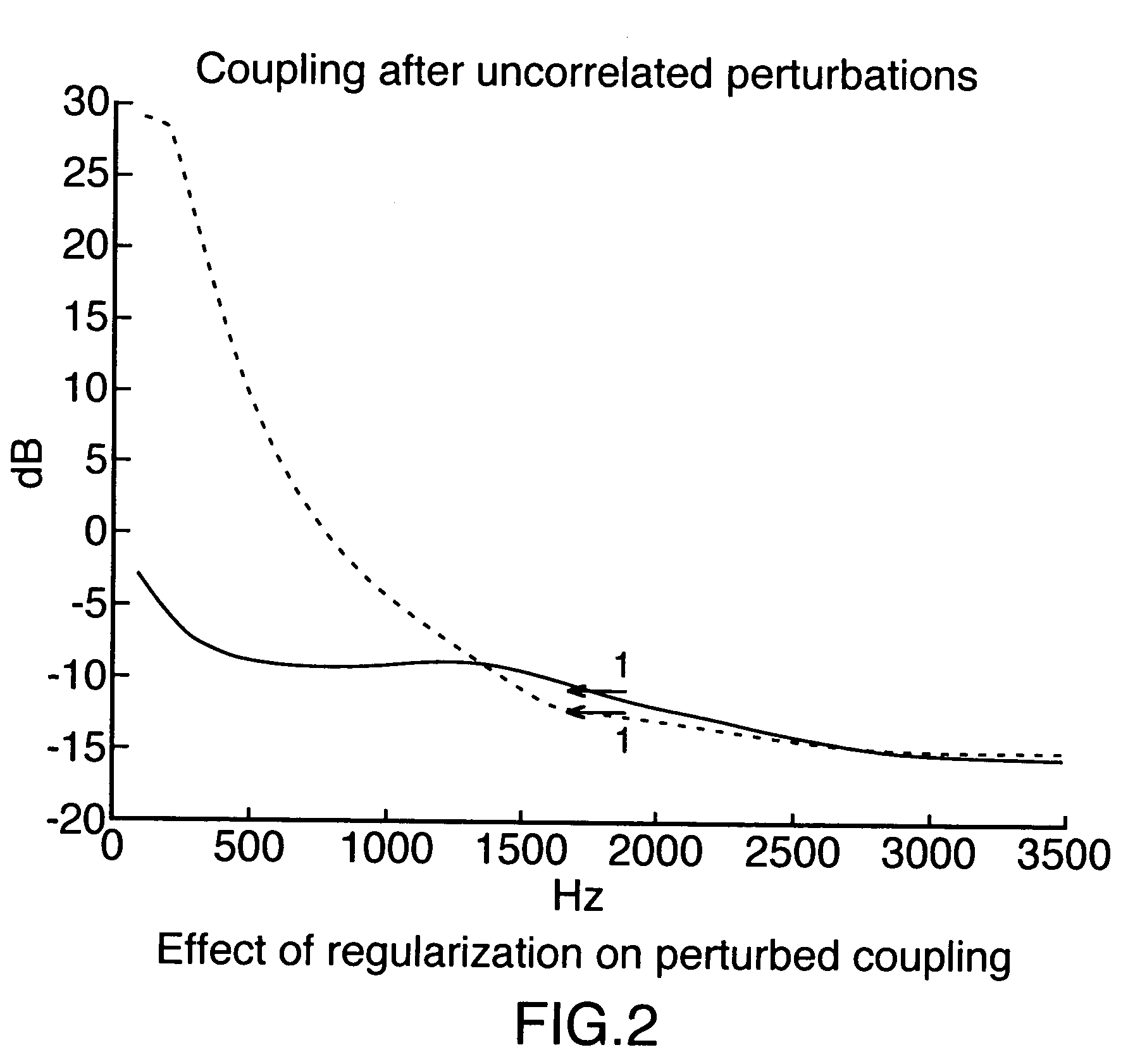
[0018]According to the foregoing, there is no need to compromise between directivity and coupling characteristics in the same beamformer design. The resulting system provides enhanced near-end speech quality (reverberations and local interference are suppressed by the “near-end” directional beamformer) as well as enhanced full-duplex operation (loudspeaker feedback is reduced by the “far-end” beamformer that is used in the presence of far-end signal or double-talk).
[0019]The present invention is to be distinguished from half-duplex echo cancellation, wherein the transmit channel is closed during far-end speech activity and partially closed during double-silence. In the present invention, both sound pickup schemes can be designed to provide a similar gain and frequency response towards the near-end talker. The resulting audio conferencing system therefore provides true full-duplex communication, and switching between the two sound-pickup schemes is much less noticeable for the far-end listener than it is with a half-duplex system. Furthermore, the full-duplex conferencing system benefits from maximal directivity when required (i.e. during near-end speech and possibly double-silence) as well as reduced loudspeaker-to-beam coupling performance when required (i.e. during far-end speech, double-talk and possibly double-silence).

Problems solved by technology

Furthermore, the full-duplex conferencing system benefits from maximal directivity when required (i.e. during near-end speech and possibly double-silence) as well as reduced loudspeaker-to-beam coupling performance when required (i.e. during far-end speech, double-talk and possibly double-silence).

Method used


Image

  • Method to reduce acoustic coupling in audio conferencing systems
  • Method to reduce acoustic coupling in audio conferencing systems
  • Method to reduce acoustic coupling in audio conferencing systems

Examples


Embodiment Construction

[0021]FIG. 5 is a flowchart of the method steps according to the present invention. Upon receipt of a new sample or block of samples, the full-duplex acoustic echo cancellation control logic detects between near-end speech and far-end speech and outputs the results of its detection (i.e. far-end speech detected, near-end speech detected or near-end speech not detected). In the event that far-end speech is detected, the far-end speech sound-pickup scheme is used. That is, a beamformer is switched in to process the signal samples with good coupling characteristics for far-end-speech, double-silence and double-talk. In the event that near-end speech is detected, the near-end speech sound-pickup scheme is used. That is, a beamformer is switched in to process the signal samples with good directivity towards the near-end speaker. Similarly, if neither far-end nor near-end speech is detected, then the far-end speech sound-pickup scheme is used. As mentioned above, an alternative implementa...


PUM


Abstract

A method to reduce acoustic coupling in an audio conferencing system having a loudspeaker and a plurality of microphones, comprising detecting the presence of one of either a source of near-end signal or a source of far-end signal source relative to the audio conferencing system, and in the event of detecting a source of near-end signal then processing the near-end signal with high directivity towards the near-end source, and in the event of detecting a source of far-end signal or double-talk then processing the far-end signal with high coupling characteristics between the loudspeaker and microphones.

Description

BACKGROUND OF THE INVENTION[0001]1. Field of the Invention[0002]The present invention is directed to audio conferencing systems, and more particularly to a method of reducing acoustic coupling and howling effects in a full duplex audio conferencing system using beamforming.[0003]2. Description of the Related Art[0004]Beamforming technology (also known as microphone array technology) can be used for spatial directivity of sound pickup in a conferencing system to enhance the quality of near-end speech. For such systems that perform full-duplex communications, acoustic echo cancellation presents numerous challenges.[0005]One problem that is well known in the art relates to combining acoustic echo cancellation with beamforming (see M. Brandstein and D. Ward, “Microphone Arrays. Signal Processing Techniques and Applications”. Springer Verlag, 2001, and H. Buchner, W. Herbordt, W. Kellermann, “An Efficient Combination of Multi-Channel Acoustic Echo Cancellation With a Beamforming Micropho...

Claims


Application Information

Patent Timeline
Patent Type & Authority Patents(United States)
IPC IPC(8): H04M9/08H04B7/06H04R3/02H04R27/00
CPCH04R27/00H04B7/0617H04R2430/20H04R3/02
Inventor BEAUCOUP, FRANCKTETELBAUM, MICHAEL
Owner MITEL
Learn More