Multi-color X-ray generator

a generator and multi-color technology, applied in the direction of x-ray tube targets, nuclear engineering, x-ray tubes, etc., can solve the problems of subject change, drop in the quality of reconstructed images, and inability to introduce facilities even for research or medical treatment, and achieve the effect of satisfying the requirement of precise image pickup

Active Publication Date: 2010-05-25
IHI CORP +2
View PDF11 Cites 2 Cited by
  • Summary
  • Abstract
  • Description
  • Claims
  • Application Information

AI Technical Summary

Benefits of technology

[0046]Moreover, a wavelength of the X-ray generated by the collision of the pulse electron beam with the pulse laser light is determined depending on a wavelength of laser light. When the plurality of pulse laser lights having the different wavelengths are generated by the composite laser generator, two or more types of monochromatic hard X-rays can successively be switched and generated at short time intervals.
[0047]Furthermore, since the pulse laser lights head-on collide with the pulse electron beam along the rectilinear orbit to generate the monochromatic hard X-rays, collision efficiency can be maximized.
[0049]Moreover, since the pulse laser units can generate the pulse laser lights in a short period (e.g., 10 pps or more), the laser control unit controls the plurality of pulse laser lights have a time difference. In consequence, the plurality of pulse laser lights are allowed to successively head-on collide with the pulse electron beam in a short period, and two or more types of monochromatic hard X-rays can successively be switched and generated in the short period (e.g., 10 pps or more).
[0050]Therefore, the wavelengths of the X-rays can successively be switched at high speed without physically moving any device or component, a change of a wavelength switch time of a subject can be suppressed and satisfactorily precise image pickup can be performed.

Problems solved by technology

However, a synchrotron radiation light facility in which a synchrotron is used is a large-sized facility in which the synchrotron has a large diameter of about 50 m or more and an orbit length reaches 100 m or more, and there is therefore a problem that the facility even for a research or the medical treatment cannot easily be introduced.
In the two-color X-ray CT, if much time is required for the switching of the energy, there is a problem that a state of a subject changes and a quality of the reconstructed image drops.
However, in the monochromatic meter, since a crystal angle needs to be precisely adjusted, it is very difficult to switch the monochromatic meter in the short time.
Moreover, even in another X-ray source in which the particular X-ray is used as a monochromatic X-ray, the target needs to be switched physically, and it is also difficult to switch the target at the high speed.
Furthermore, in a case where the mixed two-color X-ray obtained by mixing the dominant wave X-ray and the double higher harmonic wave X-ray are mixed is extracted from the synchrotron radiation light as in Non-Patent Document 2, the wavelength of the X-ray is limited to that of the higher harmonic wave, and there is also a problem that the dominant wave cannot be separated from the higher harmonic wave.
In addition, in “X-ray Generation Device” of Patent Document 1, the wavelength of the laser light cannot be switched in the short time.
Moreover, “X-ray Generation Device” of Patent Document 2 has problems that the device has a small collision probability between the pulse-like electron beam and the first and second laser lights and a low X-ray generation output.

Method used


Image

  • Multi-color X-ray generator
  • Multi-color X-ray generator
  • Multi-color X-ray generator

Examples


first embodiment

[0060]FIG. 5 is a diagram of a multi-color X-ray generator according to the present invention. As shown in this drawing, the multi-color X-ray generator of the present invention includes an electron beam generator 10, a composite laser generator 20 and a laser light introduction device 30.

[0061]The electron beam generator 10 has a function of accelerating an electron beam to generate a pulse electron beam 1, and transmitting the beam along a predetermined rectilinear orbit 2.

[0062]In this example, the electron beam generator 10 includes an RF electron gun 11, an α-magnet 12, an acceleration tube 13, a pending magnet 14, Q-magnets 15, a deceleration tube 16 and a beam dump 17.

[0063]The RF electron gun 11 and the acceleration tube 13 are driven by a high-frequency power source 18 of an X-band (11.424 GHz). An orbit of the electron beam drawn from the RF electron gun 11 is changed by the cc-magnet 12, and the beam then enters acceleration tube 13. The acceleration tube 13 is a small-si...

second embodiment

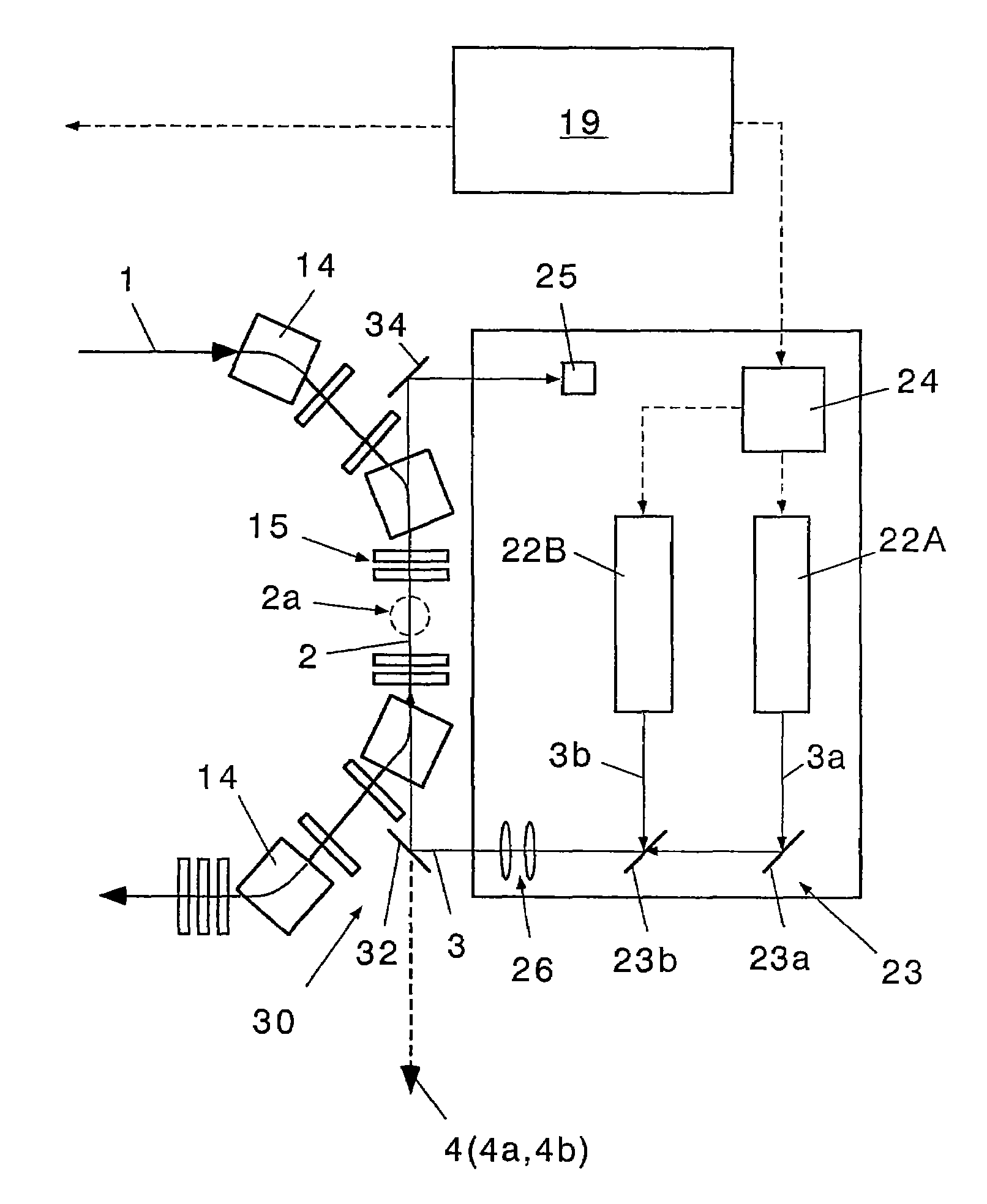
[0086]FIG. 7 is a diagram of a multi-color X-ray generator according to the present invention. In this example, a composite laser generator 20 further has a laser circulation system 28.

[0087]In this example, the laser circulation system 28 includes a total reflection mirror 28a and a half mirror 28b. The total reflection mirror 28a reflects pulse laser light 3 transmitted along a rectilinear orbit 2 and reflected by a second mirror 34 toward the half mirror 28b. The half mirror 28b is a half mirror through which the pulse laser light 3 can be transmitted as it is and which reflects the pulse laser light 3 from the total reflection mirror 28a toward a first mirror 32 of a laser light introduction device 30.

[0088]According to this constitution, the pulse laser light 3 transmitted along the rectilinear orbit 2 is circulated along an optical path before transmitted along the rectilinear orbit 2, and the same pulse laser light 3 can be circulated to collide with a pulse electron beam 1a ...


PUM


Abstract

A multi-color X-ray generator includes an electron beam generator 10 which accelerates an electron beam to generate a pulse electron beam 1 and which transmits the beam along a predetermined rectilinear orbit 2, a composite laser generator 20 which successively generates a plurality of pulse laser lights 3a, 3b having different wavelengths, and a laser light introduction device 30 which introduces the pulse laser lights along the rectilinear orbit 2 to be opposed to the pulse electron beam 1, so that the plurality of pulse laser lights 3a, 3b successively head-on collide with the pulse electron beam 1 along the rectilinear orbit 2 so as to generate two or more types of monochromatic hard X-rays 4 (4a, 4b).

Description

[0001]This is a National Phase Application in the United States of International Patent Application No. PCT / JP2006 / 309504 filed May 11, 2006, which claims priority on Japanese Patent Application No. 139726 / 2005, filed May 12, 2005. The entire disclosures of the above patent applications are hereby incorporated by reference.BACKGROUND OF THE INVENTION[0002]1. Field of the Invention[0003]The present invention relates to a multi-color X-ray generator which successively switches and generates two or more types of monochromatic hard X-rays at short time intervals[0004]2. Description of the Related Art[0005]X-rays are electromagnetic waves having a wavelength of about 0.1 to 100 A (10−11 to 10−8 m), among the rays, an X-ray having a short wavelength (10 to 100 keV, λ=1 to 0.1 A) is referred to as a hard X-ray, and an X-ray having a long wavelength (0.1 to 10 keV, λ=100 to 1 A) is referred to as a soft X-ray. Moreover, an X-ray emitted at a time when an electron beam or the like is struck ...

Claims


Application Information

Patent Timeline
Patent Type & Authority Patents(United States)
IPC IPC(8): H01J35/00
CPCG21K5/00H01J35/14H05G2/00H01J35/28H01J2235/08
Inventor NOSE, HIROYUKIISHIDA, DAISUKEKANEKO, NAMIOSAKAE, HISAHARUUESAKA, MITSURUDOBASHI, KATSUHIRO
Owner IHI CORP
Why Eureka
Try Eureka