Fiber optic shape sensor
a fiber optic and shape sensor technology, applied in the field of shape sensing, can solve the problems of limited 3d point resolution, fbg size limits the measurement resolution, and disadvantages of current optical fiber shape sensing methods, and achieve the effect of facilitating calculation
- Summary
- Abstract
- Description
- Claims
- Application Information
AI Technical Summary
Benefits of technology
Problems solved by technology
Method used
Image
Examples
example 1
A. EXAMPLE 1
[0115]Referring to FIG. 7, a kinematic chain of four links coupled to retain two DOF's of bending can be described by an overall kinematic model:
[pktk]=fkin({right arrow over (q)}1,{right arrow over (q)}2) (20)
[0116]The sensing segment start frame is defined in the first link, and the sensing segment end frame is defined in the second link. The three cases of the sensing fiber attached to both links, attached in the first link and unconstrained at the tip to slide in a tight cylindrical conduit in the second link, or attached in the second link and unconstrained to slide in a tight cylindrical conduit in the first link, can all be described by the goal function:
Min with respect to {right arrow over (q)}1,{right arrow over (q)}2 of {Abs(ts−tk)} (21)
[0117]This function describes that the fiber segment end is constrained to have the same orientation with respect to the fiber segment start as the second link has with respect to the first link. Given that the orientation me...
example 2
B. EXAMPLE 2
[0118]Referring to FIG. 10, a single-DOF rotational joint {right arrow over (q)}1 can be described by the kinematic model of the form:
[pktk]=fkin({right arrow over (q)}1) (22)
[0119]The sensing segment start frame is defined in the first (proximal) link, and the sensing segment end frame is defined in the second (distal) link. The sensing fiber may be attached in the first link and unconstrained to slide in a tight, cylindrical conduit in the second link, or the sensing fiber may be attached in the second link and unconstrained to slide in a tight, cylindrical conduit in the first link. The associated goal function is:
Min with respect to {right arrow over (q)}1 of {Abs(ts−tk)} (23)
[0120]Given that the orientation measurement ts has two DOF's (it is a unit vector), {right arrow over (q)}1 is determined, and the measurement noise can be minimized too.
[0121]In another implementation, the fiber may be constrained in a slit (rather than in a cylindrical conduit) in either or...
example 3
C. EXAMPLE 3
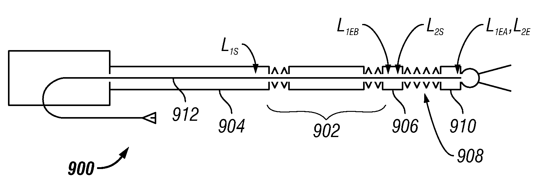
[0122]Referring to FIG. 9A, mechanism 902 illustrates a kinematic chain of seven links and additional mechanical constraints that enforce the parallelism of the output link 906 with respect to shaft 904 so that two DOF's {right arrow over (q)}1 and {right arrow over (q)}2 are sufficient to describe the overall kinematics according to a model of the form:
[pktk]=fkin({right arrow over (q)}1,{right arrow over (q)}2) (25)
[0123]The sensing segment start frame is defined in the first link (shaft 904) and the sensing segment end frame is defined in the second link (link 906). The sensing fiber may be attached in the first link and unconstrained to slide in a tight, cylindrical conduit in the second link, or the sensing fiber may be attached in the second link and unconstrained to slide in a tight, cylindrical conduit in the first link. The associated goal function that describes that the fiber end segment position with respect to the fiber start segment position in the plane o...
PUM
 Abstract
Description
Claims
Application Information
 - R&D
- Intellectual Property
- Life Sciences
- Materials
- Tech Scout
- Unparalleled Data Quality
- Higher Quality Content
- 60% Fewer Hallucinations
Browse by: Latest US Patents, China's latest patents, Technical Efficacy Thesaurus, Application Domain, Technology Topic, Popular Technical Reports.
© 2025 PatSnap. All rights reserved.Legal|Privacy policy|Modern Slavery Act Transparency Statement|Sitemap|About US| Contact US: help@patsnap.com


