
Method and system for forming reinforcing fibers and reinforcing fibers having particulate protuberances directly attached to the surfaces

a technology of reinforcing fibers and fibers, which is applied in the field of method and system for forming reinforcing fibers and reinforcing fibers having particulate protuberances directly attached to the surfaces, can solve the problems of composite product strain or failure, increase costs, and difficult manufacturing and processing, and achieve the effect of rapid bonding

Active Publication Date: 2010-05-18
JOHNS MANVILLE CORP
View PDF5 Cites 35 Cited by
  • Summary
  • Abstract
  • Description
  • Claims
  • Application Information

AI Technical Summary

Benefits of technology

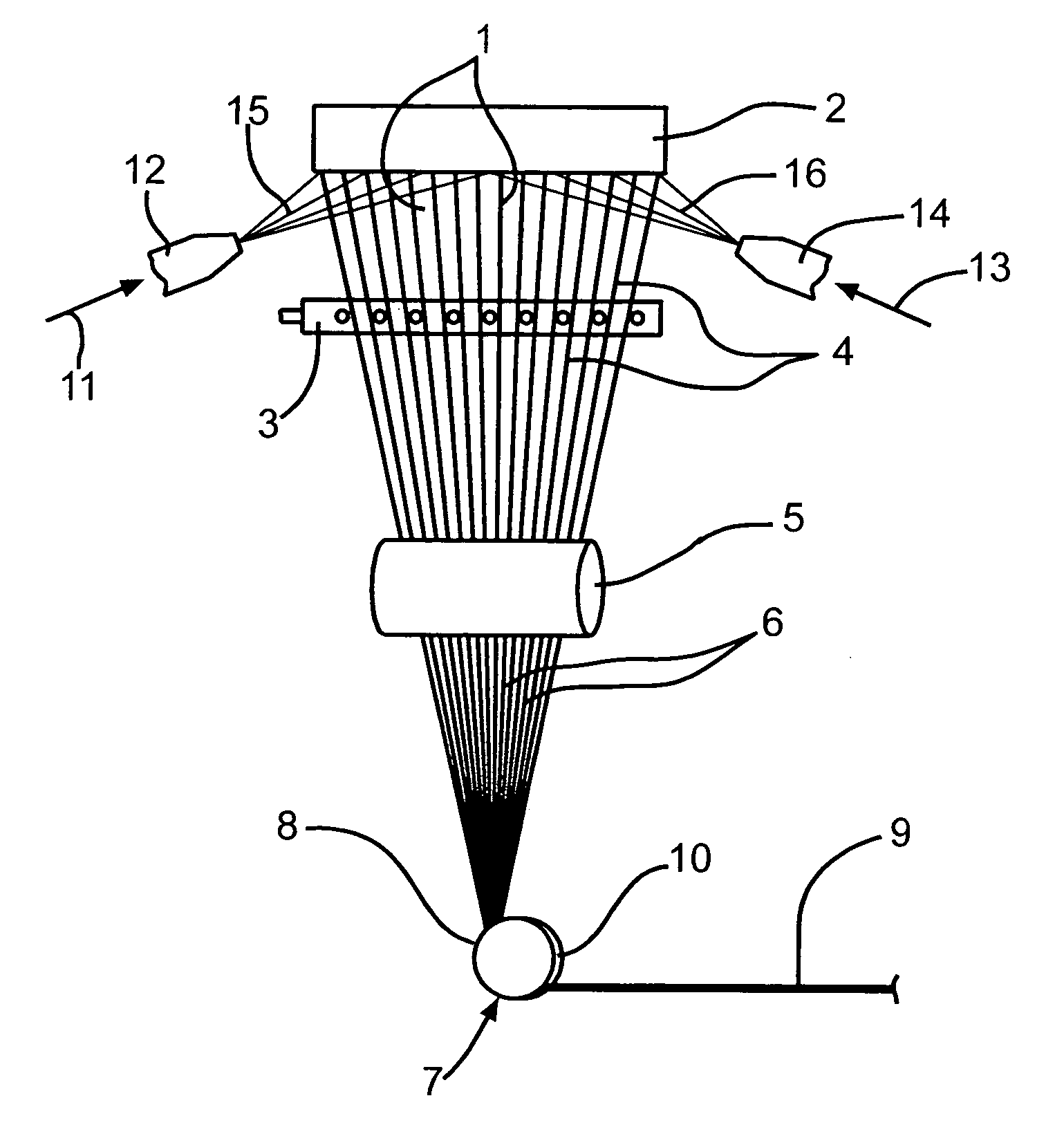
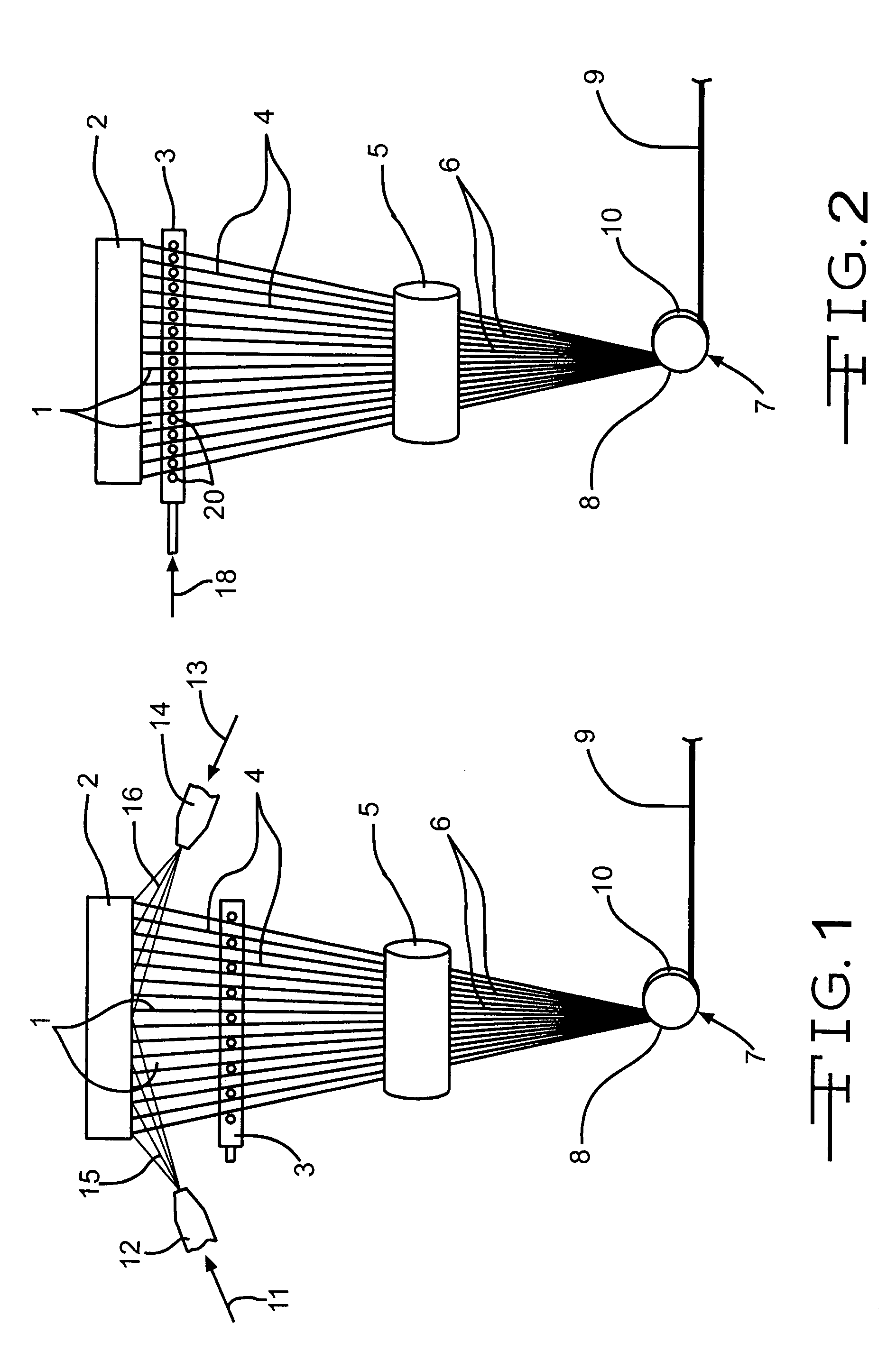
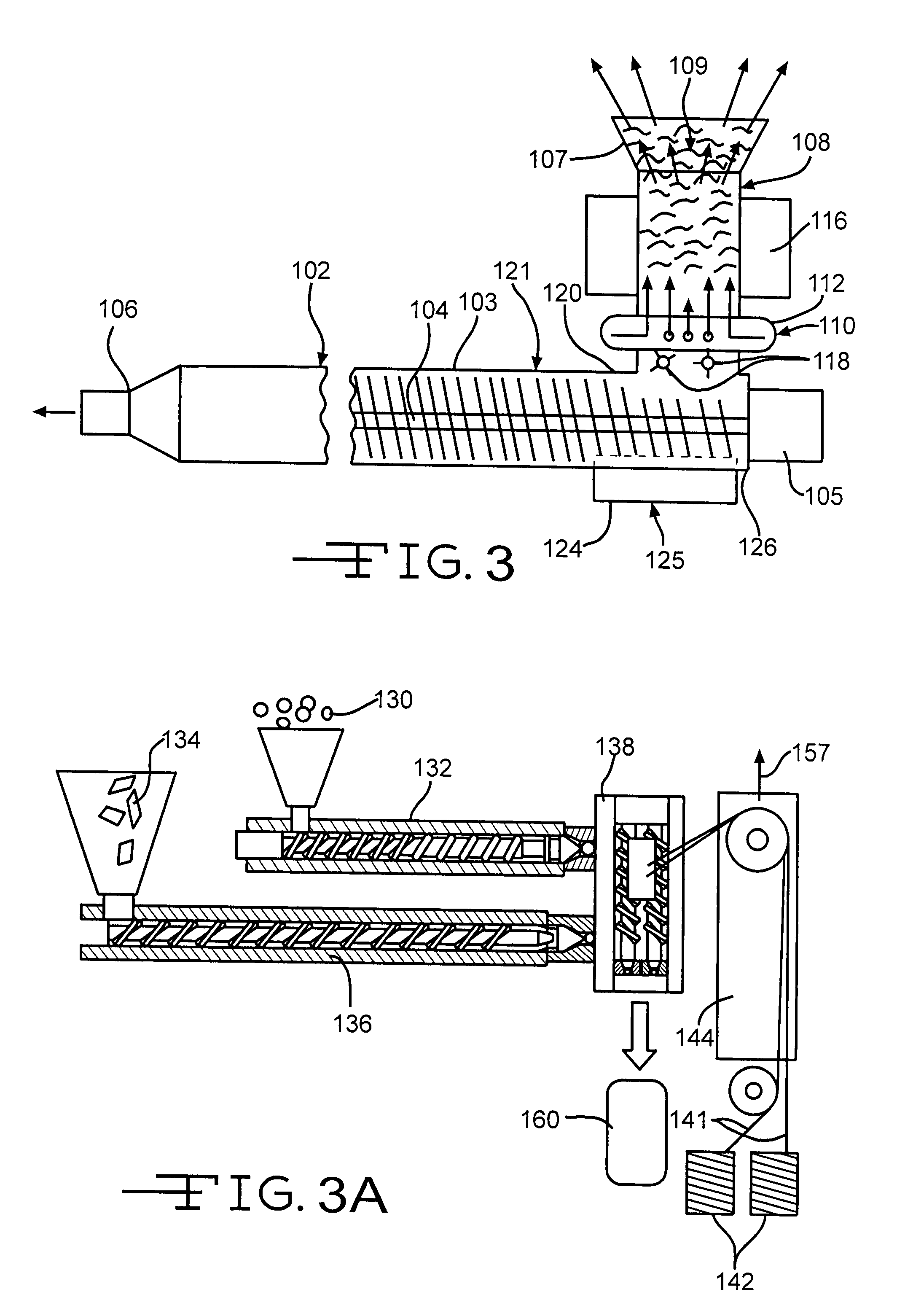
The present invention relates to reinforcing fibers with particulate protuberances bonded directly to the fiber surface. The fibers can be made of various materials such as glass, ceramic, metal, or polymer and can be coated with typical sizing materials or binders. The particles can be any compatible with the matrix they are reinforcing, such as oxides, carbides, metals, or organometallic compounds. The particles can be preheated and suspended in gaseous streams or collected in strands. The fibers can have short or long lengths and can be used in composite materials with toughness and strength similar to conventional LFRP products. The method of forming the fibers involves directing particles onto the fiber surface while it is still in a molten state. The particles can be irregularly shaped and contain voids. The invention provides stronger and more tough composite materials with improved performance.

Problems solved by technology

Once the bond between the matrix and the surface of the reinforcing fiber is broken, the matrix can slip away from the fiber thereby causing strain or failure of the composite product.
Reducing the diameter of the reinforcing fibers increases its surface area, but also increases costs and makes the manufacturing and processing more difficult.
This aids the fiber handling characteristics, but may not be good for later processing and may affect the final product characteristics.
Filamentation, the breaking down of the fiber bundles resulting in excessive small fiber bundles and individual fibers in the product, causes bridging in the feeding bin cones, and other fiber handling equipment resulting in costly scrap and downtime.
The time and amount of mixing action to accomplish this has a practical limit, and because of the strength of the bonds between the fibers, high-shear mixing commonly is required to achieve an acceptable degree of fiber dispersion and wet out (coating of the fibers with the polymer or polymer mixture).
This shear damages the fiber surface and breaks the fibers into shorter segments, and commonly still falls short of optimum fiber dispersion.
As a result, the produced reinforced plastic parts commonly do not reach their full potential with respect to surface characteristics and physical properties.
However, processing of long chopped glass fibers using standard equipment is not feasible due to the damage that the fibers would sustain under the high shear mixing and difficulties in dispersing of these long fiber bundles.
In contrast, short fibers are easy to process and disperse, but they do not provide optimum properties within the composite materials.
It is not difficult for the artisan or others to determine whether such an embodiment is either as expected, or because of either a break in the continuity of results or one or more features that are significantly better than those reported by the inventor, is surprising and thus an unobvious teaching leading to a further advance in the art.

Method used


Image

  • Method and system for forming reinforcing fibers and reinforcing fibers having particulate protuberances directly attached to the surfaces
  • Method and system for forming reinforcing fibers and reinforcing fibers having particulate protuberances directly attached to the surfaces
  • Method and system for forming reinforcing fibers and reinforcing fibers having particulate protuberances directly attached to the surfaces

Examples


Embodiment Construction

[0027]Typically, chopped fiber made and used in the invention will be at least approximately 3 mm long on average, but shorter fibers can be used. Longer chopped fibers can be as long as approximately 250 mm on average, with a more typical range being between approximately 7 mm and approximately 100 mm on average, most typical being in the range of approximately 12 mm to approximately 50 mm on average. The majority of the fibers in the chopped strands typically have diameters of from approximately 6 micrometers to approximately 50 micrometers on average, preferably from approximately 10 to approximately 23 micrometers on average, but other diameters may be suitable for some applications. Microfibers, with diameters less than approximately 6 micrometers also may be converted into the fibers of the present invention. Customarily, most of the fibers will be in a narrow range of fiber diameters and lengths, because this is how most reinforcing fiber products on the market are made, but ...


PUM

PropertyMeasurementUnit
number average diameteraaaaaaaaaa

Abstract

Reinforcing fibers with small particles having a longest average dimension of approximately 0.01 nanometer to approximately 30 micrometers physically and / or chemically bonded directly to their surfaces to form protuberances thereon and a method and system for making these modified fibers are disclosed. The particles directly bonded to the surfaces of the fibers, serve to enhance physical properties of composite articles which incorporate such fibers as reinforcement.

Description

[0001]This invention includes a method and system for forming reinforcing fibers having particulate protuberances directly attached to the surfaces thereof that render such fibers well suited for incorporation in a matrix material to form a fiber reinforced composite article. The resulted fibers can be used to form fiber reinforced products (FRP) or long fiber reinforced products (LFRP) having one or more of improved physical properties, lower cost, better fiber dispersion, better fiber adherence to the matrix material, improved appearance, fewer defects, particularly surface defects, and better uniformity including surface uniformity.BACKGROUND OF THE INVENTION[0002]It has long been known to make reinforcing fibers of glass, ceramics, carbon and certain polymers such as aromatic polyamides, etc. It has also long been known to coat the fibers with a sizing composition that protects the surfaces of the fibers against abrasive damage and enhances the bonding of a polymer or other matr...

Claims


Application Information

Patent Timeline
Patent Type & Authority Patents(United States)
IPC IPC(8): B05D1/12
CPCC03C25/1005C03C25/143D04H1/42D06M23/08C08J5/24C08J5/06Y10T428/2927Y10T428/25D06M2200/50D04H1/4209D04H1/4218D04H1/4234D04H1/4242C03C25/465D04H1/43838D04H1/43825C08J5/04
Inventor D'SILVA, SEAN CHARLESBURGHARDT, THOMAS E.
Owner JOHNS MANVILLE CORP
Learn More