Supercharge Your Innovation With Domain-Expert AI Agents!
Vibrating and twinkling LED backlighting device
Inactive Publication Date: 2010-05-18
TUAN WEI JEI
View PDF4 Cites 6 Cited by
Summary
Abstract
Description
Claims
Application Information
AI Technical Summary
This helps you quickly interpret patents by identifying the three key elements:
Problems solved by technology
Method used
Benefits of technology
Benefits of technology
[0006](1) The light of said vibrating and twinkling device is usually concentrated in a specific spot which limits the illuminating range of the device. It also limits the application area of the device because its simple lighting effect
[0007]In accordance with the present invention, it is an objective thereof to change the illumination mode to expand the application area of the device.
[0009]It is another objective of the present invention to solve limitation of the size, improving the light efficacy and extending its range of use.
[0039](1) One of the improvement of the present invention is the light emitting device (4) whereof light emitting angle is parallel with the circuit board (31), with installation of a transparent encapsulation body (2) and a high reflectivity frame (11) can change the illuminating area of a LED (41) from a specific spot to whole surface of the encapsulation body (2) providing backlighting illumination and improvement in lightening efficacy comparing to the conventional device.
[0040](2) Another improvement of the present invention is using an encapsulation body (2) to provide better light-guiding ability. It also simplifies the structure of the device, reducing the cost, providing easier manufacture, and secures the elements inside the device. Its impermeability can protect the device against any malfunction caused by damp.
[0041](3) Other improvement of the present invention is using combination of the metal element (61), metal bead (62) and metal pole (64) to allow the ball-rolling switch (6) having adequate sensitive conductivity, when there is insufficient sensitivity the metal bead (62) won't sense the slightly vibration, producing less twinkles as expected while over sensitivity may produce too much twinkles and reducing the life of the power supply unit (5).
Problems solved by technology
(1) The light of said vibrating and twinkling device is usually concentrated in a specific spot which limits the illuminating range of the device. It also limits the application area of the device because its simple lighting effect
Method used
Image
Click on the blue label to locate the original text in one second.
Reading with bidirectional positioning of images and text.
Examples
first embodiment
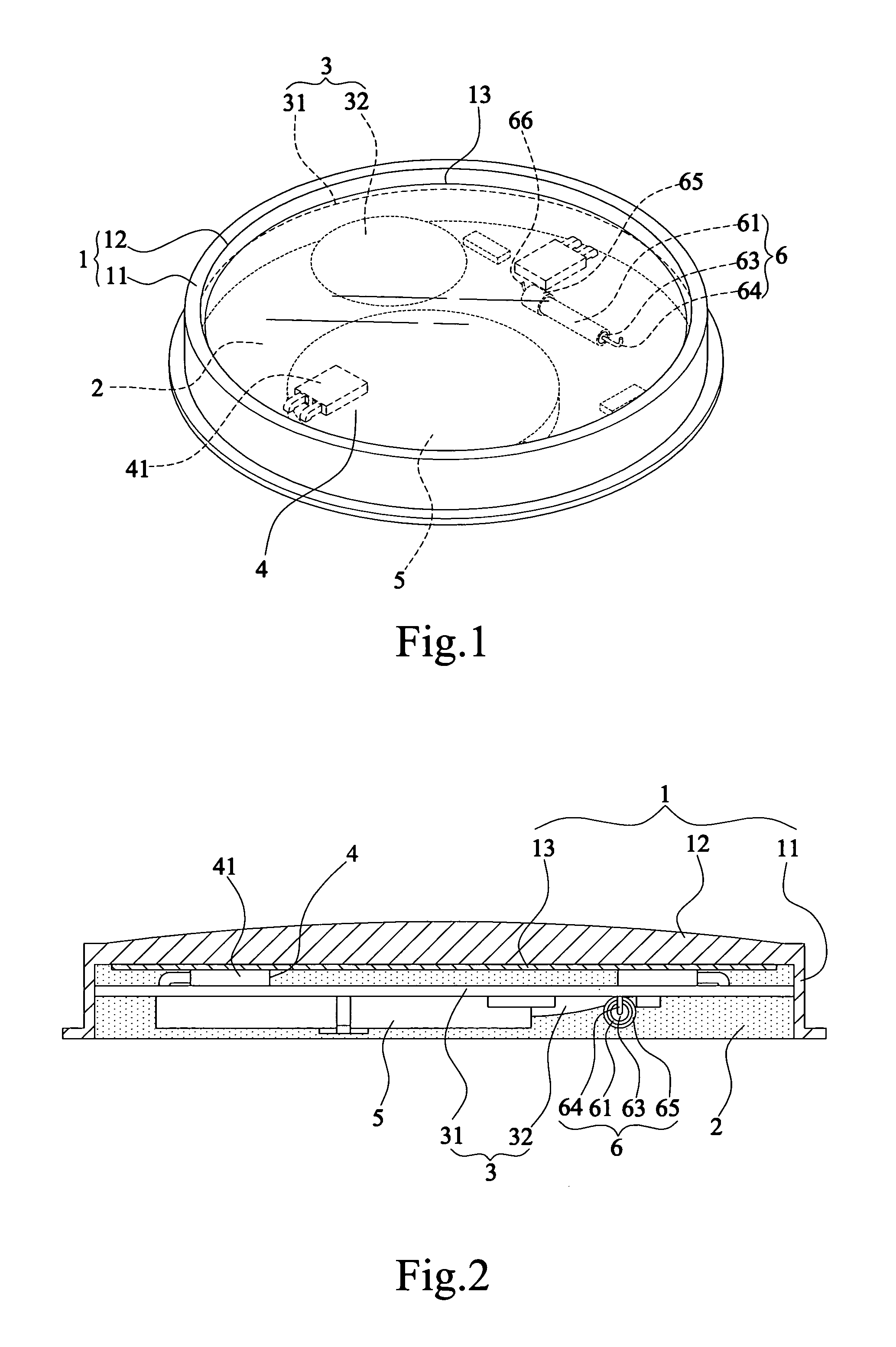
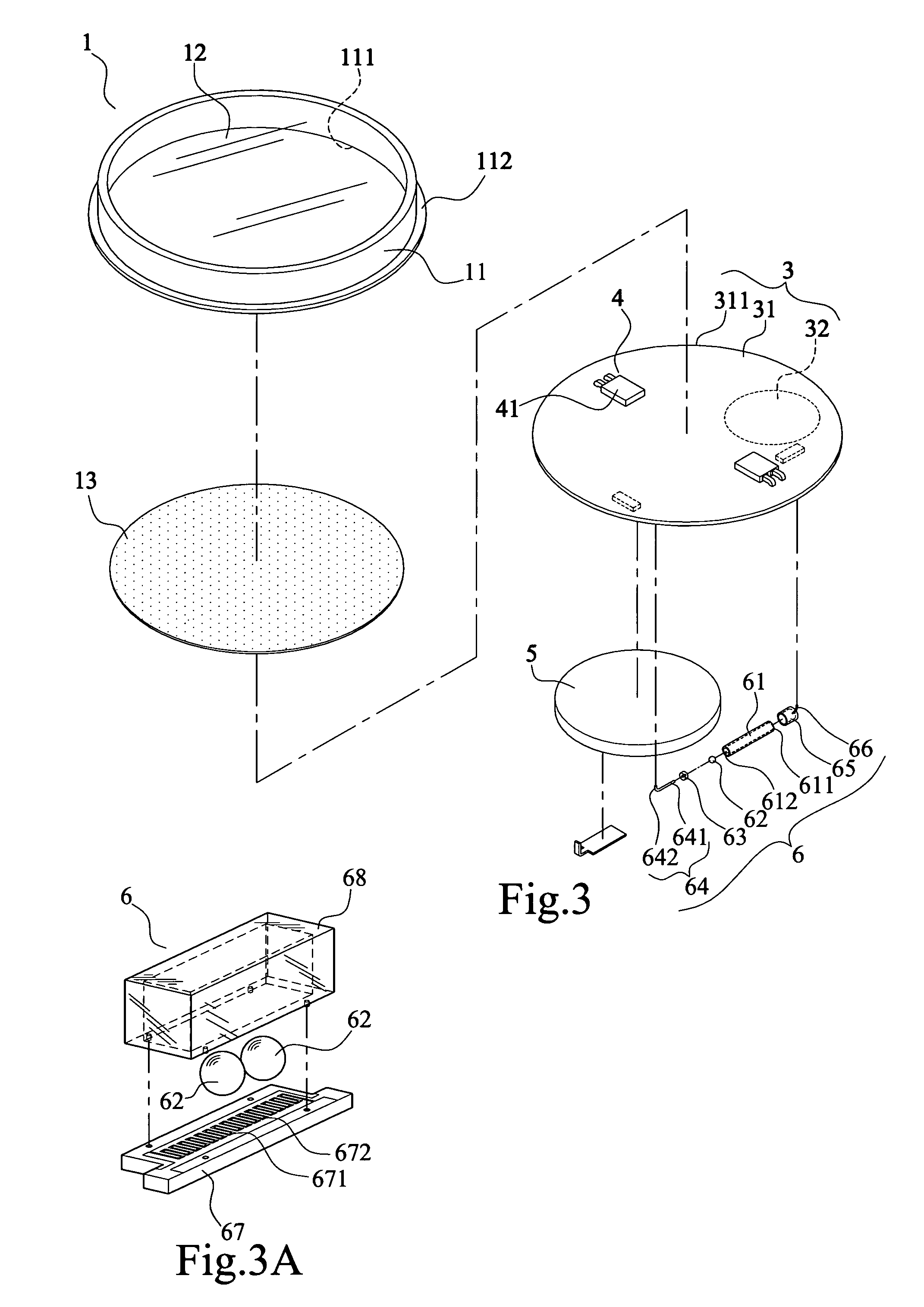
[0058]the invention as shown in FIGS. 1-3 and 3A, a main body (1) comprises an opaque, hollow and polymorphous frame (11), and a cover plate (12) which is pervious to light disposed on the top of the frame (11) and corresponds to said frame (11);
[0059]A circuit element (3), disposed inside the main body (1), said circuit element (3) comprises a circuit board (31), and a circuit-control element (32) which electrically connects with the circuit board (31);
[0060]At least one light emitting device (4), electrically connected with the circuit of the circuit board (31) and the light emitting angle is parallel with the circuit board (31); said light emitting device (4) comprises: at least one Light-Emitting Diode (LED) (41) mounted on the side of the surface of said circuit board (31) and connected electrically therewith;
[0061]A power supply (5), electrically connected with the circuit element (3) for supplying power;
[0062]A ball-rolling switch (6), electrically connected with the circuit ...
second embodiment
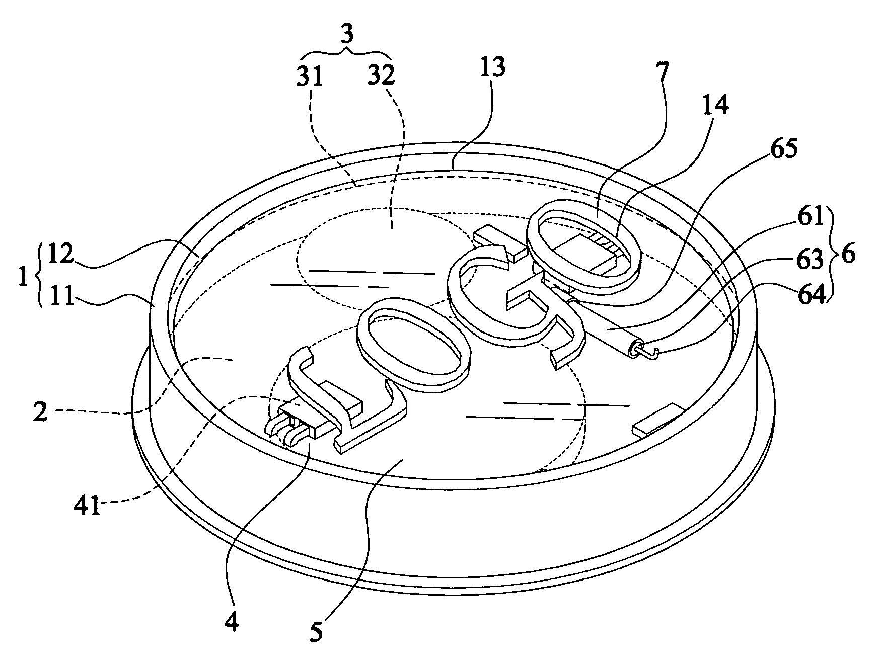
[0087]In FIGS. 7-9 showing the present invention, a groove (14) is disposed on the bottom of the cover plate (12), and a translucent or transparent decoration (7) containing letters, color or figure can fit in said groove (14). The combination of the decoration (7), cover plate (12), and LED backlighting, produced by light emitting device (4) allow the decoration (7) illuminate as a billboard, and increasing its benefit when the decoration (7) represents a logo. The chip (13) of the preferred embodiment can also be applied here.
[0088]Said LED (41) as disclosed in both preferred and second embodiment can be one of the following: multi-color LED, mono-color LED or mixture of both as required. Combination of different LED (41) may provide variety changes of the device and increase its economic value.
[0089]Moreover, said encapsulation body (2) can be made by following material: EPOXY, reaction adhesive (commonly known as AB glue) or silica gel. Utilization of said flexible adhesives for...
PUM
Abstract
A waterproof vibrating and twinkling LED backlighting device includes: a main body (1), said main body (1) comprises a light-tight, hollow and polymorphous frame (11), and a transparent cover plate (12) installed on top of said frame (11); a circuit element (3), said circuit element (3) comprises a circuit board (31) and a circuit-control element (32) electrically connects with the circuit board (31); at least one light emitting device (4) which electrically connects with the circuit board (31), and its light emitting angle is parallel with the circuit board (31), said light emitting device (4) comprises: at least one Light-Emitting Diode (LED) (41) mounted on the side of the surface of said circuit board (31) and connected electrically with which; a power supply (5); a ball-rolling switch (6) electrically connects with the circuit element (3); and a transparent encapsulation body (2) filled inside the main body (1) to cover the circuit element (3), power supply (5) and ball-rolling switch (6).
Description
FIELD OF THE INVENTION[0001]The present invention relates to a vibrating and twinkling LED backlighting device with variety uses.DESCRIPTION OF PRIOR ART[0002]The creation of LED (Light-Emitting Diode) helps the development of the semi-conductor industry; with technology advancing everyday, today's LED is smaller, brighter, and being used in our daily life more and more often. Lots of devices that we could only find in our imagination or science fiction before are now happening in the real life, such as the vibrating and twinkling LED backlighting device.[0003]A conventional vibrating and twinkling device is consisting essentially of a circuit board, a LED electrically connects to the circuit board, an integrated circuit (IC) to control the twinkling of LED, a battery to supply power, and a vibrating switch to switch on / off operation of the device. Said vibrating and twinkling device has small size, but it can provide better lighting and twinkling effect. As decoration, said vibrati...
Claims
Application Information
Patent Timeline
Application Date:The date an application was filed.
Publication Date:The date a patent or application was officially published.
First Publication Date:The earliest publication date of a patent with the same application number.
Issue Date:Publication date of the patent grant document.
PCT Entry Date:The Entry date of PCT National Phase.
Estimated Expiry Date:The statutory expiry date of a patent right according to the Patent Law, and it is the longest term of protection that the patent right can achieve without the termination of the patent right due to other reasons(Term extension factor has been taken into account ).
Invalid Date:Actual expiry date is based on effective date or publication date of legal transaction data of invalid patent.
