
Universal room extension for expandable rooms

a technology of expandable rooms and universal room extensions, which is applied in the direction of transportation and packaging, transportation items, and item transportation vehicles, etc., can solve the problems of affecting the fuel economy of the vehicle, and affecting the availability of storage space under the floor

Active Publication Date: 2010-05-18
HWH
View PDF16 Cites 15 Cited by
  • Summary
  • Abstract
  • Description
  • Claims
  • Application Information

AI Technical Summary

Benefits of technology

[0007]In one embodiment, there are drive chain assemblies on each side of the expandable room so that force is applied to each corner of the room. This arrangement creates four points of contact with the room which increases the stability and control of the room. Another benefit of this four point design is the reduction of stresses on the chains and internal components. Further, since the upper drive chain exits the structural member near the structural member's top and the lower drive chain exits the structural member near the structural member's bottom, the main cylinder or driving member can be mounted inside the structural member between the two horizontally extending portions of the chains. This allows the overall width of the mechanism to be reduced as well as keep the weight of components to a minimum.
[0008]The lift assembly controls vertical movement of the room so that when the room is fully extended, the floor of the vehicle and the floor of the expandable room are substantially flush. The lift assembly comprises at least one lift cylinder for raising and lowering the room. The lift cylinder is vertically embedded at the lower end of the structural member. The lift cylinder moves vertically in the structural member and comprises a vertically movable member that extends under the floor of the room which provides a surface for the room to slide on. Placing the lift cylinder vertically in this fashion allows the assembly to use minimal coach space for the level-out feature.
[0010]In another embodiment, the main cylinders and lift cylinders are controlled by separate circuits. The circuits are in communication with each other to alert the other when to function. This embodiment uses switches that detect the horizontal and vertical position of the room. To retract the room from its extended position, the lift assembly is activated. The horizontal retract of the room does not begin until the vertical position switch detects that the room has been lifted fully. Once fully lifted, the vertical position switch activates the horizontal retract of the room. Conversely, when the room is being extended, the room extends until the horizontal position switch detects that the room is fully extended. At this point the vertical drop would be activated and the room lowers to the fully extended position with both the interior and slide-out room floor being flush. This two circuit configuration eliminates the need for the ramp assemblies since the room is controlled in each direction by separate circuits and the lift cylinder is able to support the weight of the room during both extend and retract functions.

Problems solved by technology

The hydraulic arms that are housed under the floor are generally complex, relatively expensive, and may be unduly heavy.
Further, when the room is in the retracted position, otherwise available storage space under the floor is lost.
The additional weight also adversely affects the fuel economy of the vehicle.
With the highly competitive market in these recreational vehicles, not only weight and space but also cost and reliability of operation are important factors.

Method used


Image

  • Universal room extension for expandable rooms
  • Universal room extension for expandable rooms
  • Universal room extension for expandable rooms

Examples


Embodiment Construction

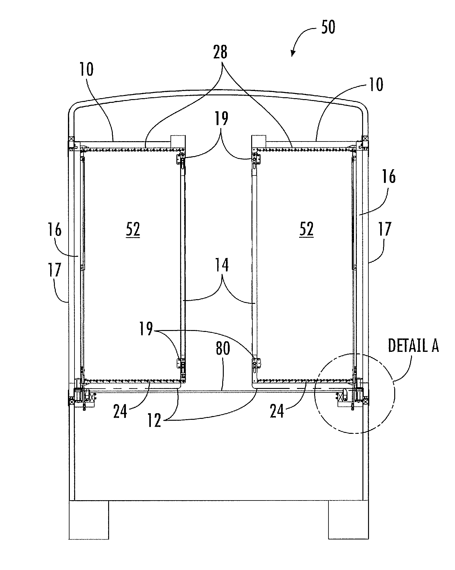
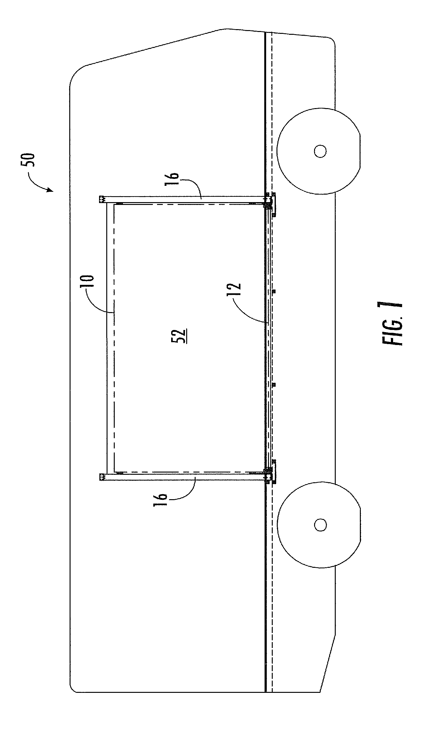
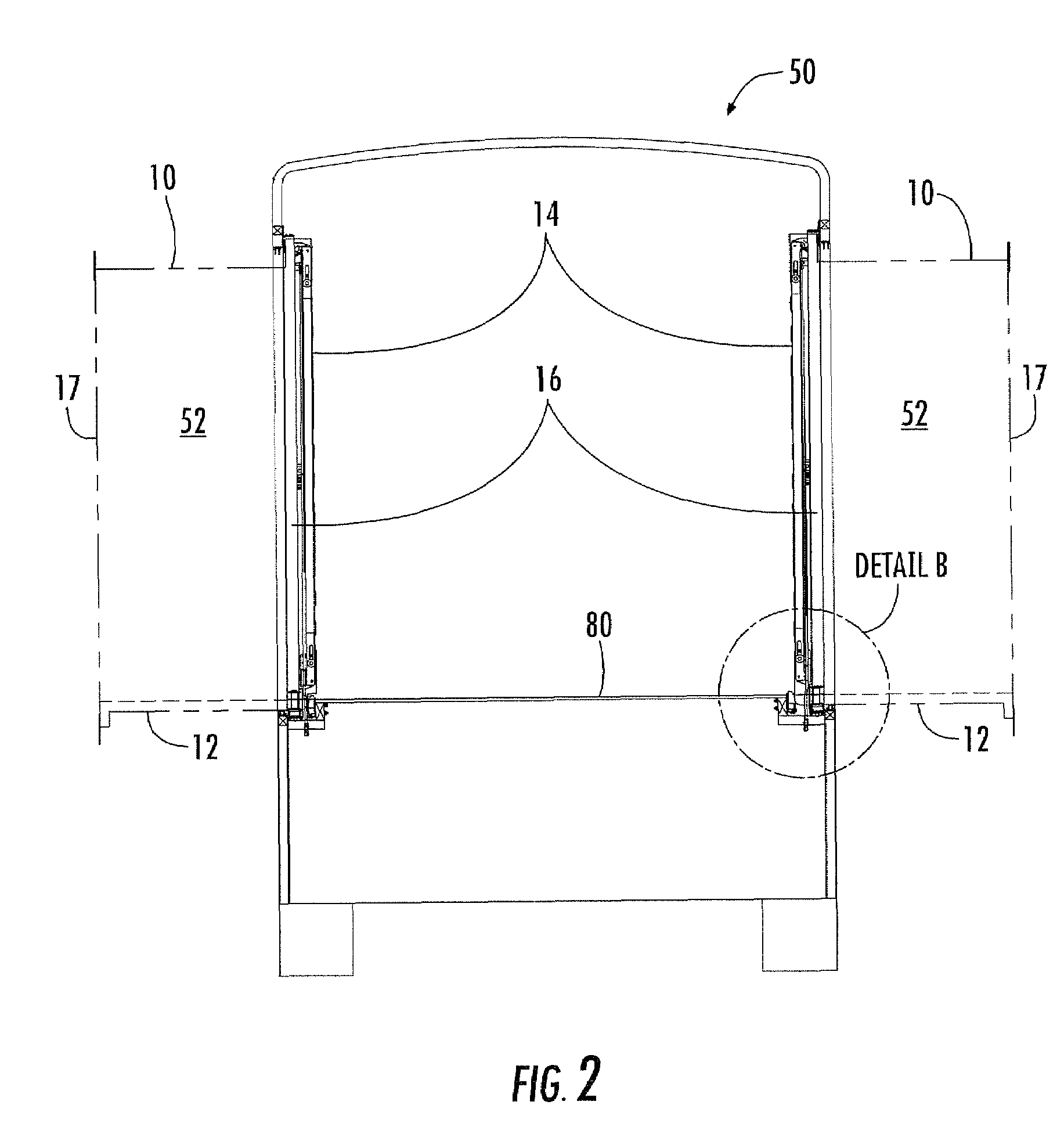
[0025]FIGS. 1, 2, and 2a illustrate a recreational vehicle 50 with at least one expandable room 52 having a drive chain assembly to control the horizontal movement of the room 52 and a lift assembly to control the vertical movement of the room 52. The invention is described herein as being applicable to an expandable room 52 that extends outwardly from a side wall of the recreational vehicle 50, but the principles of the invention are applicable to the expansion and retraction of a movable structure in other applications as well.

[0026]Referring first to FIGS. 3-7, there is illustrated a portion of the framework for an expandable room 52 for a recreational vehicle 50 which, as is know to those skilled in the art, has an opening formed in its side wall to accommodate an expandable room 52.

[0027]The expandable room 52 has an upper horizontal frame member 10 and a lower horizontal frame member 12 that form a part of an interior side wall of the expandable room 52. The upper surface of t...


PUM


Abstract

A mechanism to affect the coordinated movement of an expandable room in a recreational vehicle. The mechanism comprises a drive chain assembly and a lift assembly. The drive chain assembly has a pair of drive chains (upper and lower) that move generally vertically along vehicle structural members and then the chains are redirected for horizontal travel as the main hydraulic cylinders are actuated to extend or retract the expandable room. The movement of the upper and lower drive chains is synchronized by a rack-and-pinion mechanism. The lift assembly controls vertical movement of the room so that when the room is fully extended, the floor of the vehicle and the floor of the expandable room are substantially flush. The lift assembly comprises at least one lift cylinder for raising and lowering the room. The lift cylinder is vertically combined with the lower end of the structural member.

Description

BACKGROUND OF THE INVENTION[0001]The invention relates to a linkage arrangement for moving members together or apart in a substantially horizontal motion without a substantial shift in a direction perpendicular to the desired linear motion while still allowing the members to move a limited distance vertically under controlled conditions. Typical linkages that are commonly used for a variety of purposes involve a pair of parallel members attached pivotally to a pair of parallel linkage members to form a parallelogram. If one of the parallel members is fixed, then motion of the parallelogram linkage results in an angular motion—in or out and up or down rather than simply in or out. Other known arrangements teach a linkage arrangement of the “X” or scissors type for moving members relative to one another in a substantially linear motion. The present invention utilizes a chain driven linkage arrangement for moving the members horizontally relative to each other while allowing for contro...

Claims


Application Information

Patent Timeline
IPC IPC(8): B60P3/34
CPCB60P3/34F16G13/20
Inventor HANSER, PAUL EDMUNDBULS, VINCENT
Owner HWH
Learn More