Eureka AIR delivers breakthrough ideas for toughest innovation challenges, trusted by R&D personnel around the world.

Spectrometer for surface analysis and method therefor

a surface analysis and spectrometer technology, applied in the direction of spectrometry/spectrophotometry/monochromators, instruments, optical radiation measurement, etc., can solve the problems of reducing image quality, affecting the quality of viewed images, and affecting the quality of sample viewing geometry, etc., to achieve the effect of reducing obstruction, small cross-section, and small area

Active Publication Date: 2010-05-11
THERMO FISHER SCIENTIFIC INC
View PDF28 Cites 8 Cited by
  • Summary
  • Abstract
  • Description
  • Claims
  • Application Information

AI Technical Summary

Benefits of technology

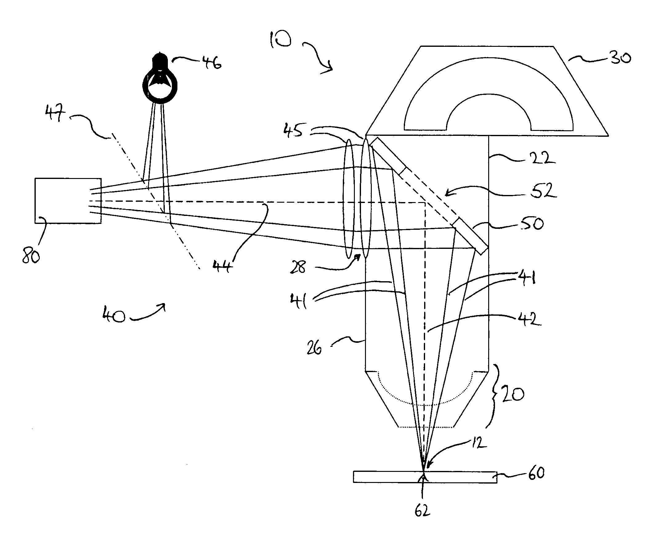
[0063]The collection lens arrangement 20 collects the secondary charged particles into the collection chamber 22 and causes the particles to converge, so that they are able to pass through the hole 52 in the mirror 50 and on to the spectroscopic analyser 30. The converging effect of the collection lens arrangement 20 may be such that the secondary particles are focused to or towards a point, either within the collection chamber 22 or the analyser 30. Alternatively, the converging effect may be such that the secondary particles are collimated into a narrow enough beam for passage through the hole 52 in the mirror 50. It is an advantage of the invention that guiding or controlling the secondary particles in any of these ways through the collection chamber 22 and into the analyser 30 does not significantly impair the collection efficiency of the spectrometer 10.
[0064]FIG. 1 shows an example in which the secondary particles are emitted with a wide range of angles from the area of analysis 62 of the sample. The emitted particles are disposed generally about the collection axis 24, which is normal to the analysis area 12 and therefore normal to the area of analysis 62 of the sample 60 which is located at the analysis area. At least a proportion of the secondary particles emitted from the surface are collected by the collection lens arrangement 20, which in this embodiment focuses them towards a point on the collection axis 24 at a downstream end of the collection chamber 22. It is noted that substantially all of the secondary particles received into the collection chamber 22 are directed through the hole 52 in the mirror 50 and onto the analyser 30.
[0065]A wide variety of analysers known in the art may be used as the spectroscopic analyser 30. For example, in energy analysis and in particular XPS or AES, the analyser 30 may be either a toroidal electrostatic analyser or an electrostatic cylindrical mirror analyser, or the analyser may be a time-of-flight analyser, especially for SIMS applications. However, any energy or mass analyser may be used, depending on the application.
[0066]FIG. 2 shows a spectrometer 10, comprising a collection lens arrangement 20 provided in a collection chamber 22, at a first end adjacent an analysis area 12 of the spectrometer, a spectroscopic analyser 30 located at the other, downstream end of the collection chamber 22, and a mirror 50 having a hole 52 therein mounted towards the downstream end of the collection chamber, as in FIG. 1. The spectrometer 10 includes an optical microscope 40, which is disposed about two optical axes in this embodiment. An objective optical axis 42 extends normally from the analysis area 12 to the mirror 50, which is mounted at a 45° angle to the objective optical axis. In this embodiment, the mirror 50 is centred on the objective optical axis 42. Extending from the centre of the mirror 50, perpendicularly to the objective optical axis 42, is an imaging optical axis 44. Disposed along the imaging optical axis 44 are two imaging lenses 45—although only one, or more, imaging lens may alternatively be used—and an optical imaging device 80, such as a CCD camera. Also disposed on the imaging optical axis 44, between the imaging device 80 and the mirror 50 is a partially reflective and partially transmissive element or pellicle 47, which is mounted at 45° to the imaging optical axis. A light source 46 is provided perpendicularly to the imaging optical axis 44 and aligned with the pellicle 47.
[0067]The collection chamber 22 is provided with a vacuum optical window 28, which is optically transmissive, so as to allow light to pass out of the collection chamber therethrough. In this embodiment, although not necessarily so, the vacuum optical window 28 provided in the side wall 26 of the collection chamber 22 is itself an optical lens element 45. This has the benefit of reducing the number of optical components in the microscope, thereby reducing cost and complexity.
[0068]In use, image light rays 41 emanating from an object at the analysis area 12, such as an area of analysis 62 of a sample 60, enter the collection chamber 22 through its entrance aperture and travel towards the mirror 50, the rays being generally disposed about the objective optical axis 42. Broadly speaking, the light rays 41 reaching the mirror 50 are reflected in a direction generally perpendicular to the objective optical axis 42, so that the reflected light rays 41 are then disposed generally about the imaging optical axis 44.

Problems solved by technology

However, the quality of the viewed image from this sample viewing geometry is generally poor, with the sample image only being truly in focus at the centre of the field of view and out of focus towards the edges, because of the angle from which the sample is viewed.
In addition, when the sample surface is illuminated by the light source, shadows formed as a result of the sample's surface topography can degrade the image quality, for the same reason.
This sample viewing geometry is therefore not desirable for identifying the analysis position.
Moreover, this system cannot be used for secondary charged particle analysis.
While visual observations with such sample viewing geometries may be of better quality, this is at the expense of potentially significant degradation in the analysis sensitivity of the instrument for the SSI X and S probe and Thermo Thetaprobe systems, due to the off-axis collection of the secondary charged particles.
While both visual and spectral observations may be made with the optical microscope axis and the collection lens arrangement axis respectively being normal to the sample surface, this approach has a significant disadvantage in that the sample cannot be optically viewed during spectral analysis.
In particular, when the source of primary particles is arranged to produce an incident beam at an oblique angle with respect to the sample surface, the area covered by such a beam is greater than when directed normally, and this can lead to excitation of a greater surface area of the sample and consequently a higher secondary particle count rate.

Method used


Image

  • Spectrometer for surface analysis and method therefor
  • Spectrometer for surface analysis and method therefor
  • Spectrometer for surface analysis and method therefor

Examples


Embodiment Construction

[0056]Referring to FIG. 1, there is shown a spectrometer 10, suitable for surface analysis of a sample 60. The spectrometer 10 is shown schematically in this embodiment and illustrates exemplary trajectories of secondary charged particles emitted from a surface of the sample 60. The spectrometer 10 comprises a collection lens arrangement 20 arranged in a vacuum collection chamber 22. Although not shown, for clarity, the vacuum collection chamber 22 forms part of a vacuum chamber which also encloses the sample.

[0057]The collection lens arrangement 20 is disposed about a collection axis 24 (which happens to be coincident with one of the illustrative charged particle trajectories 64). The collection lens arrangement 20 is located at an end of the collection chamber 22 adjacent to the analysis area 12 of the spectrometer, for reception of secondary charged particles emitted from an area of analysis 62 on the surface of a sample 60 when located at the analysis area, in use.

[0058]At the o...


PUM

PropertyMeasurementUnit
angleaaaaaaaaaa
angleaaaaaaaaaa
grazing angleaaaaaaaaaa

Abstract

A spectrometer (10) for sample surface analysis by irradiation of the surface by primary particles and a corresponding method of surface analysis spectroscopy. The spectrometer (10) provides sample viewing and secondary charged particle collection substantially normal to the sample surface. A collection chamber (22) comprises a secondary charged particle lens arrangement (20) to focus the emitted particles in a downstream direction along a first normal axis (24) and thereby to define a charged particle optical crossover location (25); and a light-reflecting optical element (50) downstream of the lens arrangement and arranged to receive image light (41) and reflect it away from a second normal axis (42) for providing a viewable image of the surface. The optical element (50) is positioned at, or near to, the crossover location (25) and comprises an opening (52) therethrough, such that the focused particles pass through the opening for downstream spectroscopic analysis substantially without obstruction by the optical element.

Description

CROSS REFERENCE TO RELATED APPLICATION[0001]This application claims priority to United Kingdom Patent Application No. GB0522060.3 filed 28 Oct. 2005, entitled “Spectrometer for Surface Analysis and Method Therefor”, which application is incorporated herein by reference in its entirety.BACKGROUND OF THE INVENTION[0002]1. Field of the Invention[0003]The invention relates to a spectrometer for surface analysis of a sample, the spectrometer having optical sample viewing capability, and to a corresponding method for surface analysis spectroscopy. The invention relates particularly, but not exclusively, to sample analysis by means of secondary electron energy spectroscopy, such as X-ray photoelectron spectroscopy or Auger electron spectroscopy.[0004]2. Description of the Related Art[0005]Chemical and physical analysis of the surface of a sample generally requires the excitation of that surface with a primary beam of “particles”, such as ions, electrons, photons or atoms, and the detection...

Claims


Application Information

Patent Timeline
Patent Type & Authority Patents(United States)
IPC IPC(8): G01N23/00H01J37/22H01J37/252
CPCH01J37/228H01J37/29H01J37/252H01J37/22H01J49/44
Inventor BARNARD, BRYAN ROBERT
Owner THERMO FISHER SCIENTIFIC INC
Why Eureka
Eureka Blog
Learn More