[0015]Another
advantage of the present invention is that it has a very
small footprint at the lens, enabling a photographer to position the
camera lens in otherwise tight spaces. Thus, the light guide allows a physical displacement of the flash tube from the object being illuminated.
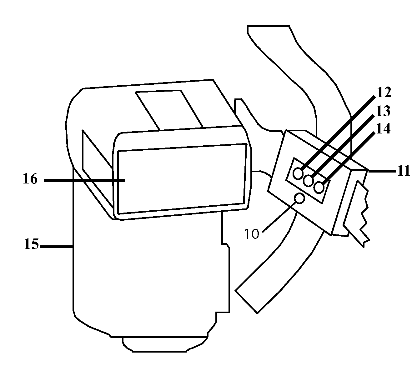
[0016]In a second embodiment, small
laser pointers (e.g., visible red LED lasers) are affixed to the ends of the
fiber optic light guides, to aid the photographer in aiming the output of the light guide. The
laser axis is therefore aligned with the axis of the light guide, and the displacement kept low. It is also possible to couple a
laser to a
fiber optic, providing a laser output within or in the center of a
fiber optic bundle. If desired, a lens or holographic filter may be provided in front of the laser, to disperse the laser to show, for example, the bounds of the light guide illumination. In addition, it is possible to use different
colored lasers for the different light guides, to allow independent adjustment without
ambiguity.
[0017]Alternately, or in addition, a modeling light may similarly be provided as a
white light emitting
diode (LED) having an illumination pattern similar to that of the stroboscopic light guide output. Various
colored LEDs may also be used to distinguish the respective sources. (The LEDs may also be used to illuminate the subject directly, but available white LEDs typically have poorer
color balance than a
xenon flash). The LEDs may also illuminate the subject through the same fiber optic bundles, either through the same fibers, or through separate fibers interspersed or bundled with the fibers which carry the stroboscopic illumination. In some cases, the subject may be fluorescent, in which case it may be advantageous to provide an
ultraviolet emitting LED to stimulate emissions; and indeed, the LED output may continue through the stroboscopic illumination.
LED illumination prior to
exposure may also excite phosphorescent emissions.
[0018]According to a further embodiment, an illumination source may be provided at the mounting to illuminate the on-camera flash tube window. The result of this is that the light is reflected back, off the rear reflector, and into the entrance apertures of the optic conduits, and hence to the exit apertures, to illuminate the subject. In this way, even when the flash tube is not illuminated, an optical output is emitted by the light guides, in generally the same pattern as the stroboscopic illuminator would produce. Thus, a modeling light is provided to permit composing of the photograph and focusing (or autofocusing) of the lens.
[0019]It is further possible to use both a primary and secondary flash in conjunction with or alternate to each other; that is, a light guide is provided from the primary flash as the
primary source, and the an independent output is provided by another illumination source, which is controlled in dependence on the primary illumination source output. Thus, for example, an LED
light source (secondary) may be driven as a slave from the normal flash (primary). The normal flash controls the timing (
initiation, duration) of the flash pulse(s) of a secondary illuminator. In this embodiment, it is possible to avoid the light conduit altogether, since a
photodetector may be placed directly over the primary flash to receive the timing information, which is then used to electronically drive the secondary illuminator, e.g., LEDs. Typically, a secondary illuminator is not necessary, and a passive light guide, such as a fiber optic illumination cable, is a preferred embodiment.
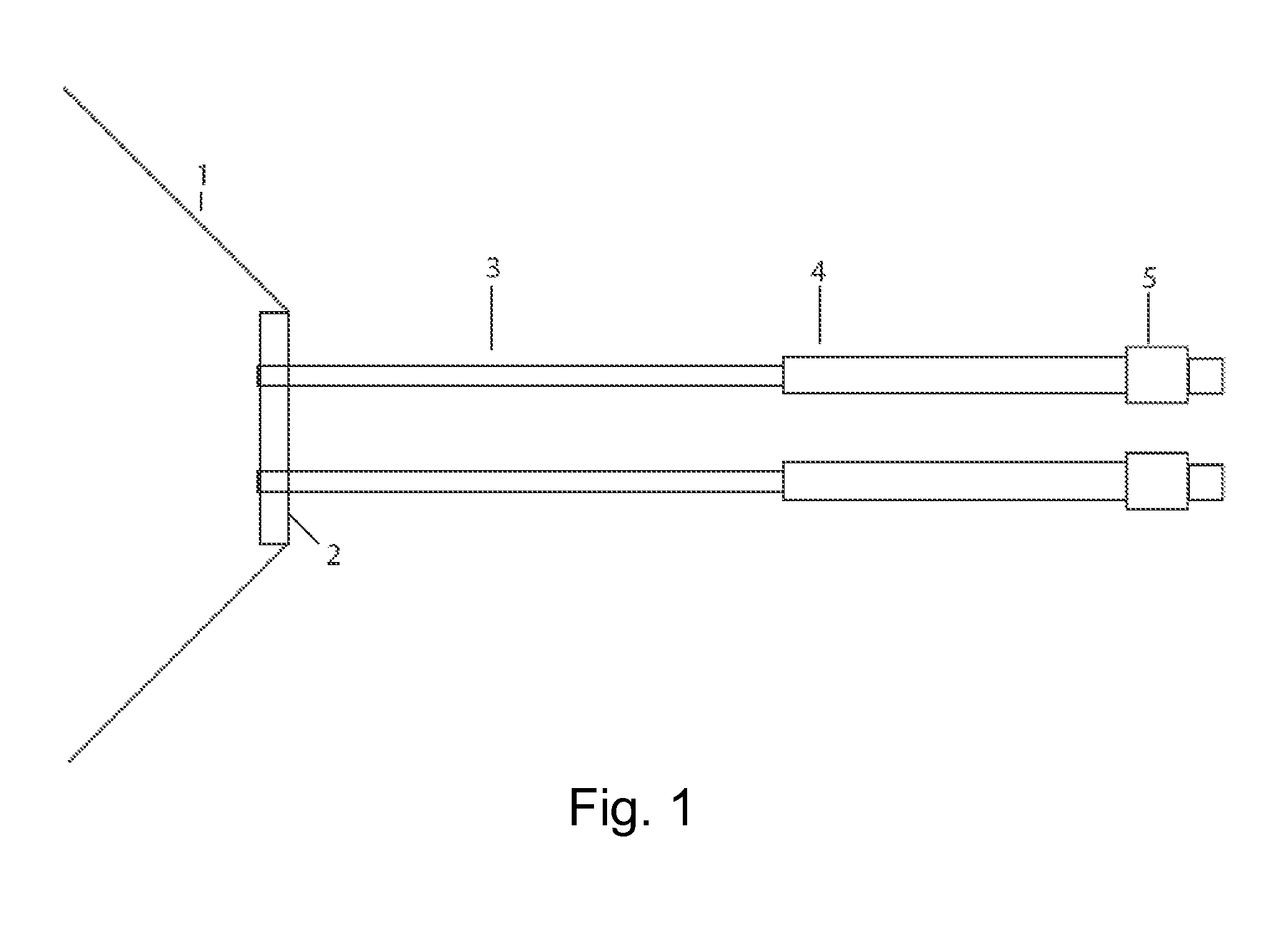
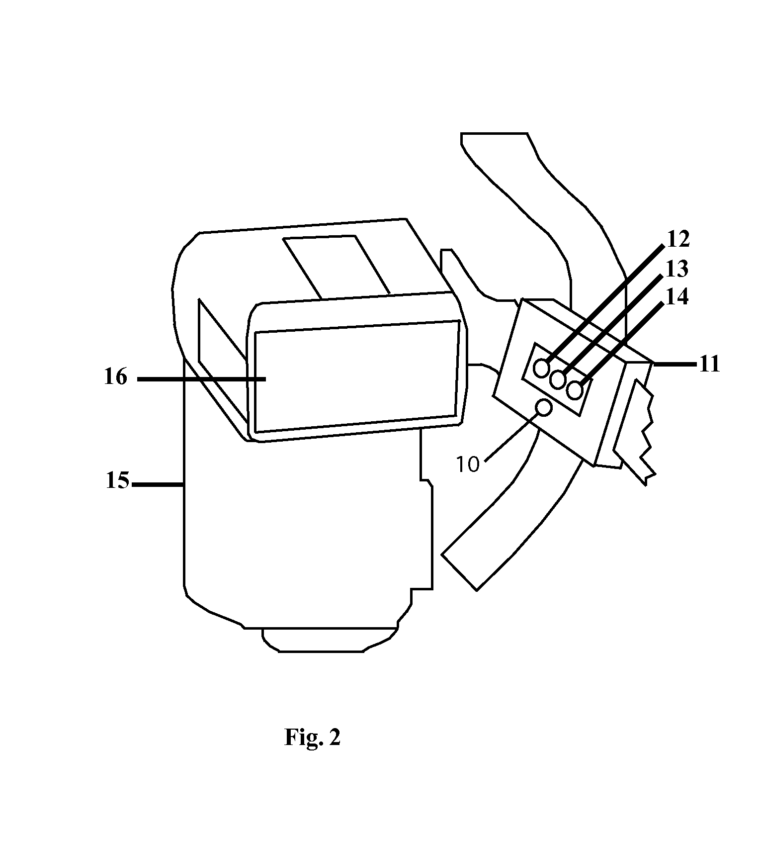
[0020]According to a preferred embodiment, the stroboscopic flash is a separate unit from the camera, which may be a through-the-lens viewing
single lens reflex digital camera. The flash, similar to on-camera units, has a rectangular window in front of a
xenon stroboscopic flash tube, which is in turn in front of a reflective surface to reflect light emitted from the rear of the tube through the window. A
mask is provided which covers the window, and which is typically opaque to prevent light from being emitted through the
mask. The
mask has a set of apertures, e.g., three apertures, each adapted to position and hold a
ferrule of a fiber optic bundle in place. The entrance face of each fiber optic bundle is held against a portion of the rectangular window, facing the tube. As noted above, the flash typically has surplus illumination, and therefore a high efficiency of light capture from the flash is not necessary, and thus a relatively small capture area (e.g., 10% of the window area for each bundle) is adequate. However, if necessary, various known means may be used to improve capture efficiency without departing from the spirit and scope of the invention. Preferably, the flash unit is not permanently modified, and the mask may be removed from the window for normal use of the flash, e.g., for non-macro photography. Therefore, one preferred way to hold the mask in place during use is through hook-and-loop (statistical) fasteners, which may be attached to the mask and flash unit outside of the window area.
