
Electrical card connector with at least a card locking mechanism

a technology of locking mechanism and card connector, which is applied in the direction of coupling device connection, two-part coupling device, instruments, etc., can solve the problems of unstable retention between the locking section and the card notch, and the plastic deformation of the locking section is always affected, so as to prevent the plastic locking section from being broken

Inactive Publication Date: 2010-05-04
HON HAI PRECISION IND CO LTD
View PDF4 Cites 16 Cited by
  • Summary
  • Abstract
  • Description
  • Claims
  • Application Information

AI Technical Summary

Benefits of technology

[0007]An object, therefore, of the invention is to provide a new and improved an electrical card connector having a reinforcement member reinforcing the plastic locking section for preventing the plastic locking section from being broken.

Problems solved by technology

But the plastic deformation of the locking section is always affected by amounts of the inserting force.
In other words, too great inserting force will cause the plastic locking section broken, and thereby lead to an unstable retention between the locking section and the notch of the card.

Method used


Image

  • Electrical card connector with at least a card locking mechanism
  • Electrical card connector with at least a card locking mechanism
  • Electrical card connector with at least a card locking mechanism

Examples


Embodiment Construction

[0015]Reference will now be made in detail to the preferred embodiment of the present invention.

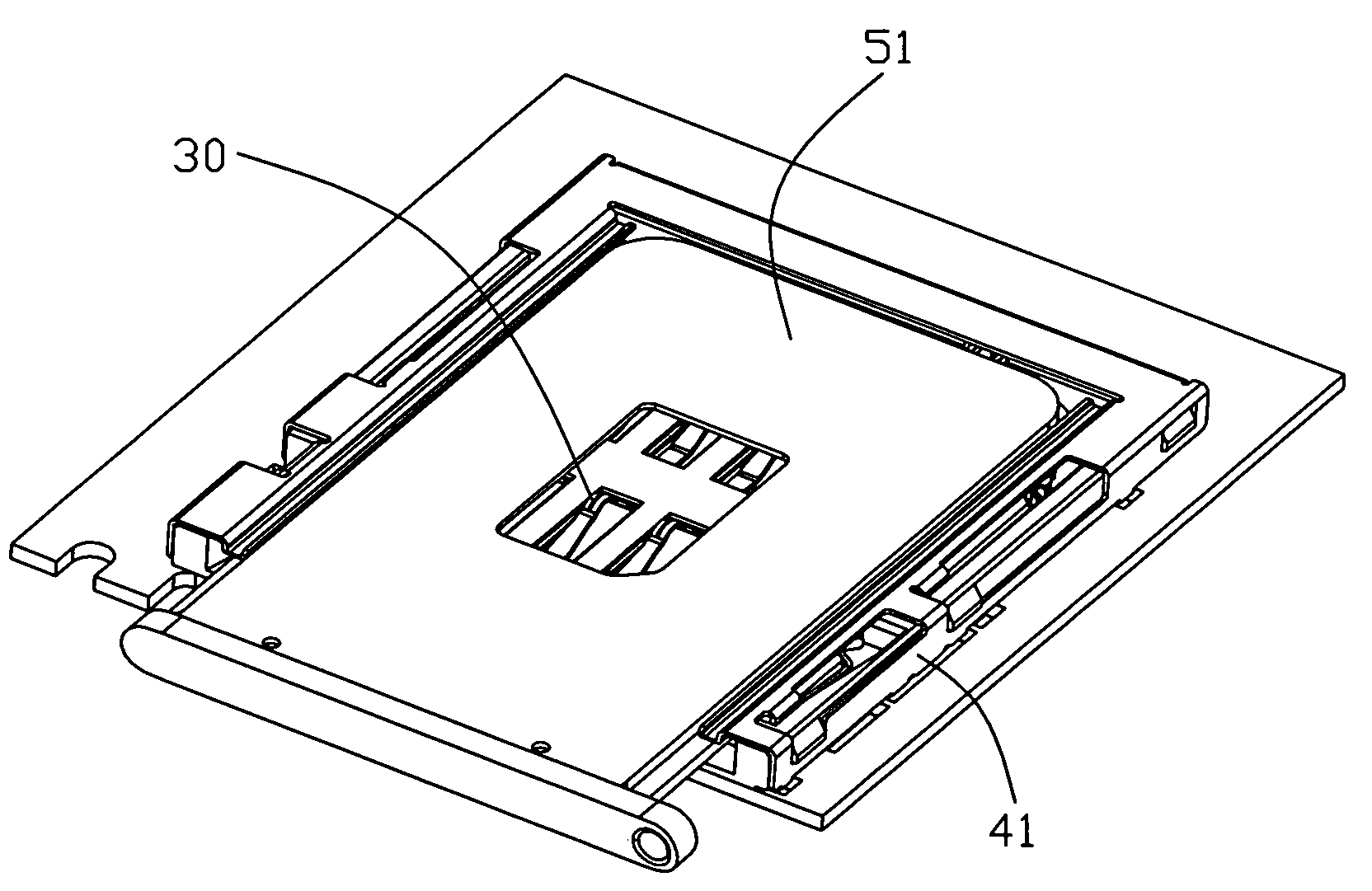
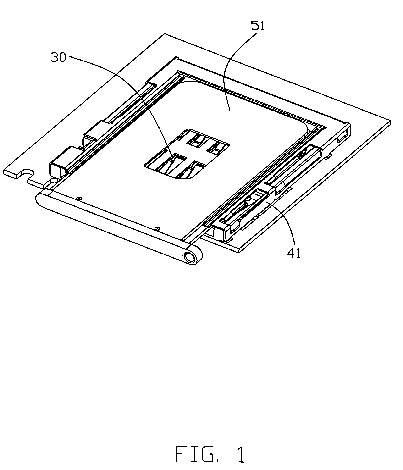
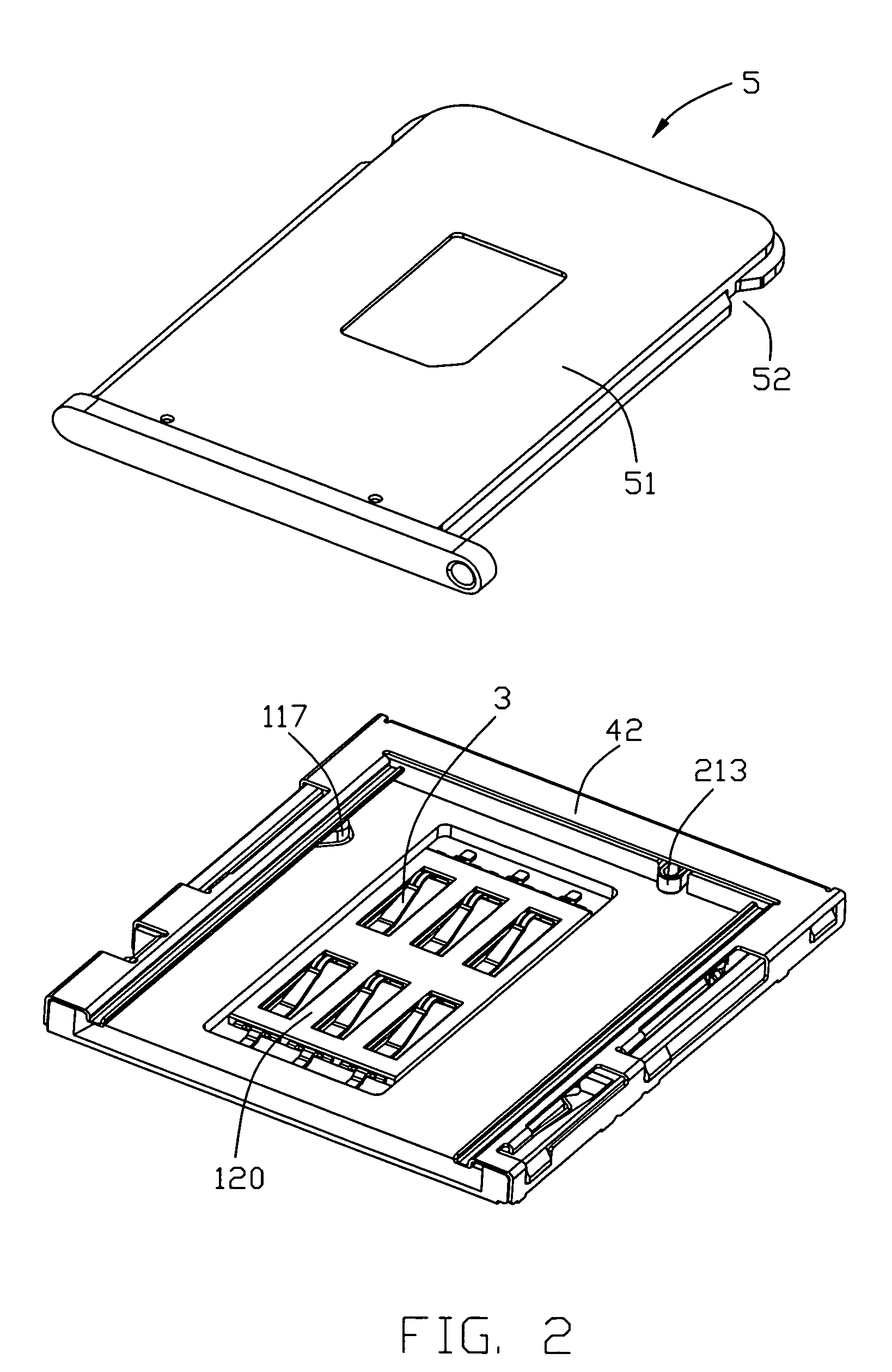
[0016]Referring to FIGS. 1-2, an embodiment of the present invention illustrated. An electrical card connector for electrically connecting an electrical card comprises an insulative housing 1 with a plurality of contacts 3 assembled therein; a detecting switch 2 defined in the insulative housing 1; a shield shell 4 covering the insulative housing 1; and a card receiving mechanism 5.

[0017]The insulative housing 1 comprises an insulative frame 11 and a terminal receiving plate 12. The insulative frame 11 includes a fundamental base 110 with an opening 111 defined therethrough. A pair of sidewalls 113 extends from two opposite sides of the fundamental base 110 with a back wall 114 defined therebetween. A receiving space 118 is defined by the sidewalls 113 and the back wall 114. Each sidewall 113 has a first groove 115 defined thereon, a beam section 116 defined in and extends along the first...


PUM


Abstract

A card connector, comprising: an insulative housing having a base, a pair of first and second raised sidewalls, and third raised sidewalls to form a receiving cavity therebetween, an insertion opening located opposite to said third raised sidewall, said base having thereon a window, each of said first and second raised sidewalls having a resilient locking arm invading laterally toward said receiving cavity; a contact module disposed within said window of the housing with a plurality of contact sections extending above a top face of the base; a metal shielding member assembled to the housing, the metal shielding member having resilient reinforcement pieces respectively located outside of said resilient locking arms.

Description

BACKGROUND OF THE INVENTION[0001]1. Field of the Invention[0002]The present invention relates to an electrical card connector, and more particularly, to an electrical card connector provided with card locking mechanisms for making the card stable in the electrical card connector to prevent the electrical card from dropping out.[0003]2. Description of Related Art[0004]Electrical cards are known in the art and contain intelligence in the form of a memory circuit or other electronic program. Some form of card readers retrieve the information or data stored on the card. Such cards are used in many applications in today's electronic society, including video cameras, digital still cameras, smart phones, PDAs, music players, ATMs, cable television decoders, toys, games, PC adapters, multi-media cards and other electronic applications, etc.[0005]Example of prior art card-receiving connectors as patent CN 2563786 of Chinese mainland comprises an insulative housing; a plurality of contacts re...

Claims


Application Information

Patent Timeline
Patent Type & Authority Patents(United States)
IPC IPC(8): H01R24/00
CPCG06K13/08G06K13/0856H01R13/65802H01R13/2442H01R12/7094H01R13/627H01R13/6582
Inventor HU, YONG-HUI
Owner HON HAI PRECISION IND CO LTD
Learn More