
Electric dual condiment grinder

a dual-motor, electric technology, applied in the field of grinders, can solve the problems wrist, soiling a table cloth, further difficulties for disabled people, etc., and achieves the effects of reducing the dexterity or mobility of the forearm, and simple construction

Inactive Publication Date: 2010-05-04
SAMSON BRIGHT IND
View PDF15 Cites 11 Cited by
  • Summary
  • Abstract
  • Description
  • Claims
  • Application Information

AI Technical Summary

Benefits of technology

[0017]This invention provides a dual condiment grinder which is ergonomically efficient in operational use. It is particularly well-suited to use by people having reduced dexterity or mobility of the forearm and wrist, who are able to operate the grinder simply by grasping and rotating it through a small angle, typically one way to dispense salt, and the other to dispense pepper. Moreover this is achieved with a design able to catch any condiment particles dislodged from or through the grinding mechanism when the grinder is generally upright. It has a simple construction employing a number of common parts for reduced manufacturing costs. It includes modular components with a low weight and inertia, it is compact, relatively efficient and quiet in operation, and is able to operate at high motor speeds.

Problems solved by technology

However, a drawback of this is that, following use, the impact caused by placing the grinder upon a table tends to dislodge condiment particles from or through the grinding mechanism which drop from the grinder and, for instance, may soil a table cloth.
However, an inverted grinder of this type has ergonomic drawbacks as it is necessary to rotate the grinder approximately 180° to dispense the ground condiment and this can be troublesome for people having reduced mobility of the forearm and wrist.
Moreover, operating a switch to initiate grinding at the same time as rotating the grinder in this manner can pose further difficulties to disabled people.

Method used


Image

  • Electric dual condiment grinder
  • Electric dual condiment grinder
  • Electric dual condiment grinder

Examples


Embodiment Construction

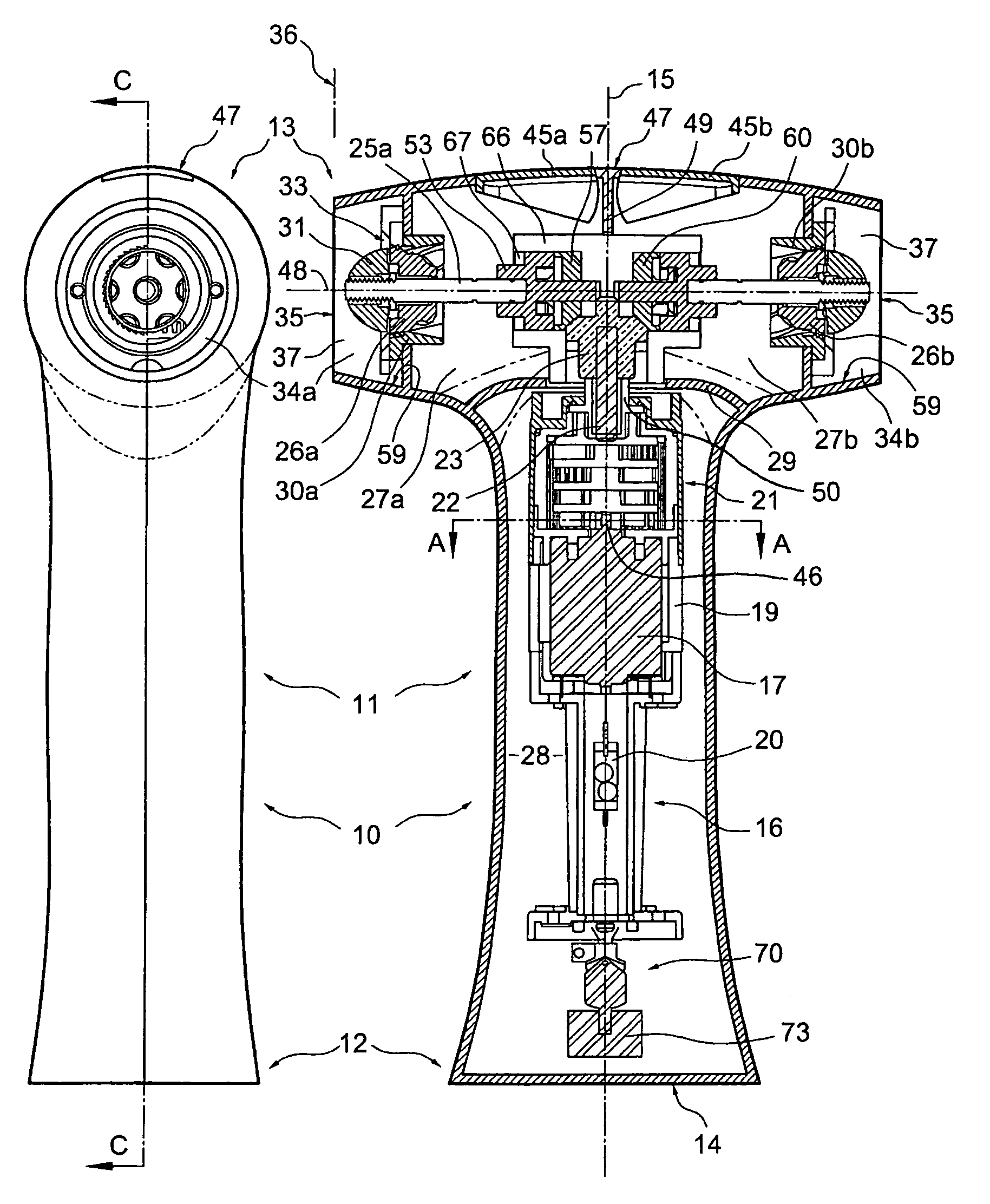
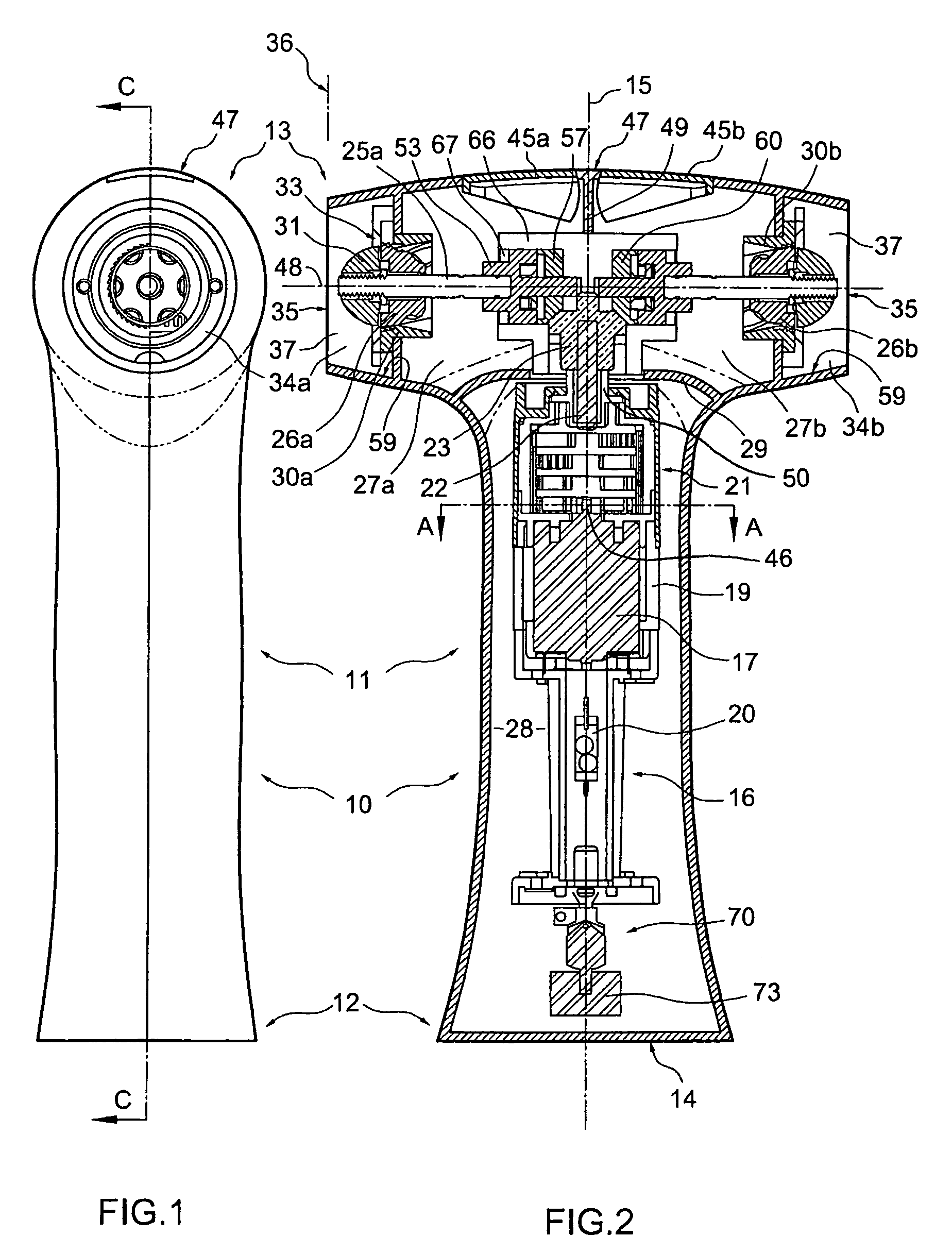
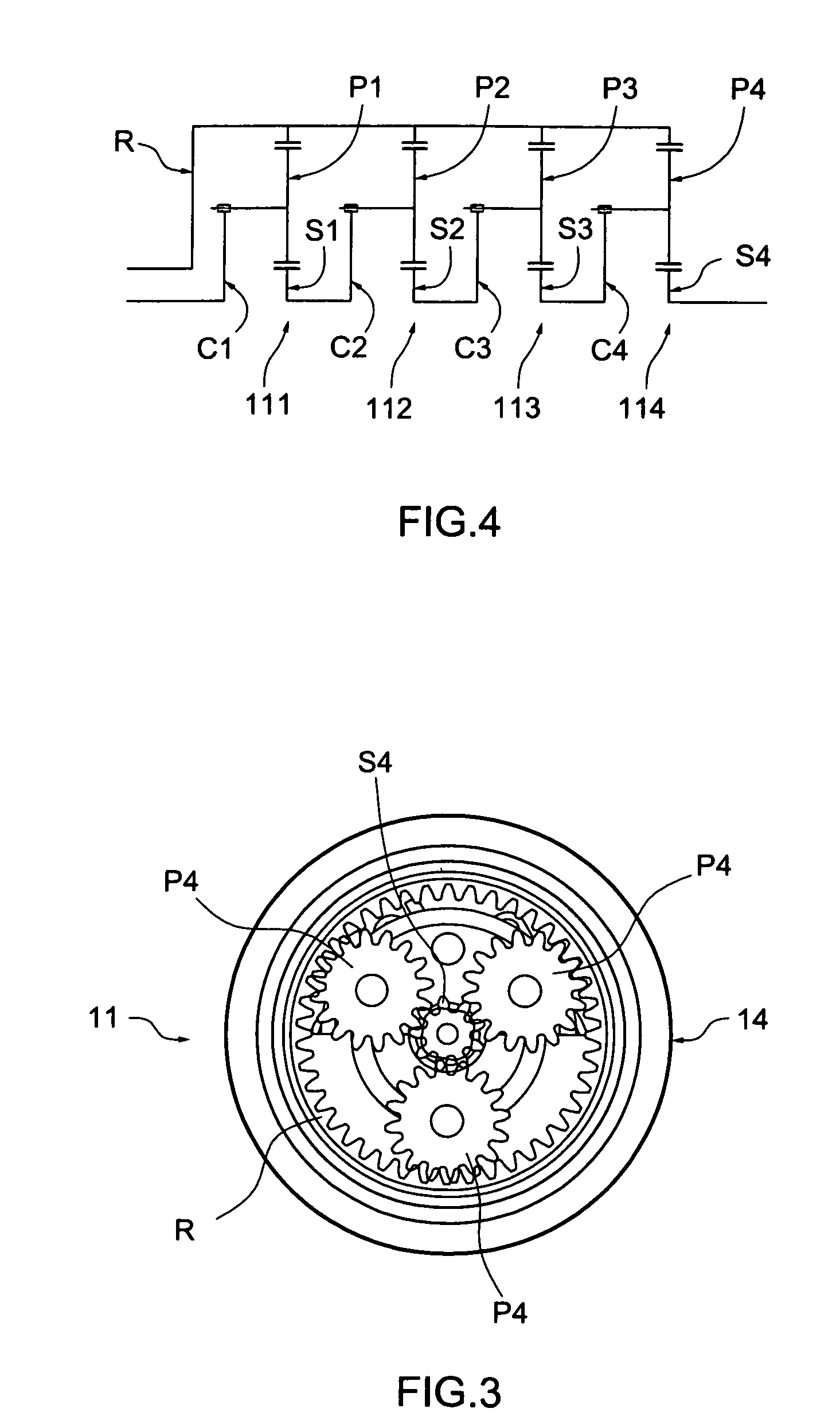
[0025]Referring to FIGS. 1-5 of the drawings, a hand-held cordless electric dual condiment grinder according to an exemplary embodiment of the invention includes a hollow housing 10 having a substantially symmetrical waisted form, with an elongate waist portion 11 which provides a grip for holding the grinder. The waist portion 11 separates the base 12 from the top 13 which both have relatively broader dimensions. The base 12 has a planar face 14 for supporting the grinder upright on a horizontal surface, the face 14 extending orthogonally to a longitudinal upright axis 15 of the waist portion 11. The hollow waisted housing 10 is assembled from two T-shaped shells 10a, 10b having a bulbous top 13 with convex top surface 47 and opposing lateral openings 41a, 41b aligned with a first transverse axis 48. Disposed in the top 13 either side of the axis 15 are first and second condiment-receiving reservoirs 27a, 27b bounded externally by the housing walls and internally by the transverse ...


PUM


Abstract

A cordless electric dual condiment grinder includes a hollow housing elongated to extend between a base for supporting the grinder uprightly and an opposing top, the top of the housing having a bulbous form to define two condiment reservoirs (e.g. for receiving salt and pepper respectively). A unidirectional rotary grinding mechanism is disposed in a lateral opening in each of the reservoirs. The lateral openings are on opposing sides of the housing and a tilt switch controls the direction of rotation of a reversible drive motor. One-way clutches in the transmission are provided such that each grinding mechanism is selectively rotated depending upon the direction of rotation of the motor output. The user can thus selectively dispense from one or other of the compartments by rotating the grinder through an acute angle from the upright such that the selected lateral opening faces downwardly and thus is particularly suited for use by people with limited dexterity.

Description

TECHNICAL FIELD[0001]The present invention relates to grinders for dispensing two ground condiments, such as pepper and salt, and particularly to grinders driven by electric motorsBACKGROUND OF THE INVENTION[0002]Hand-held cordless electric grinders provide a convenient and fast method for dispensing freshly ground pepper, salt, or other condiments. A conventional grinder of this type has an elongate housing which defines a grip by which the grinder is held and which has first and second longitudinally opposing ends. A battery compartment at the first end of the housing provides power to an electric motor connected via a speed reduction geartrain to a drive shaft. The drive shaft extends through a condiment reservoir to a grinding mechanism at the second end of the housing. In an upright design the second end may be supported on a table, or a like horizontal surface, when not in use. However, a drawback of this is that, following use, the impact caused by placing the grinder upon a ...

Claims


Application Information

Patent Timeline
Patent Type & Authority Patents(United States)
IPC IPC(8): A47J42/44
CPCA47J42/46A47J42/44
Inventor TANG, WING SUM
Owner SAMSON BRIGHT IND
Learn More