
Optical interferometric pressure sensor

a pressure sensor and optical diaphragm technology, applied in the direction of fluid pressure measurement, instruments, manufacturing tools, etc., can solve the problems of increasing the cost of measurement, affecting the accuracy of measurement, and affecting the sensitive sensor characteristic, so as to achieve mechanical stability, reduce cost, and suffer less from temperature expansion distortion

Active Publication Date: 2010-05-04
INFICON HLDG AG
View PDF19 Cites 11 Cited by
  • Summary
  • Abstract
  • Description
  • Claims
  • Application Information

AI Technical Summary

Benefits of technology

This solution provides a high-accuracy, stable, and economically viable fiber optic membrane pressure measuring cell capable of measuring high pressures at elevated temperatures with improved linearity, repeatability, and relative resolution, while minimizing the impact of environmental disturbances.

Problems solved by technology

However, in vacuum applications pressure sensors of this type are normally usable only for higher pressures in the range of approx.
High resolution at pressures below 10−1 mbar is no longer achievable with silicon.
One of the reasons for this is that the silicon surface reacts with the environment which impairs the sensitive sensor characteristic.
The problem becomes even more serious when the sensor is used in chemically aggressive atmospheres and especially with higher temperature up to some hundreds degree Celsius.
Such measures are costly and in the case of mechanically deformable parts such as membranes have only limited success, in particular in highly aggressive media such as fluorine, bromic acid and their compounds which are typically used in vacuum etching processes.
A disadvantage with using sapphire alone in the sensor cell is its price—machined single-crystal sapphire is very expensive.
Secondly, having a combination of sapphire and ceramic Al2O3 introduces a small mismatch in the Coefficient of Thermal Expansion (CTE), which might pose problems in the temperature drift behavior, for example.
To reduce this effect requires proper crystal orientation, an expensive and time consuming process.
In addition a large number of components are needed which makes the production of such a sensor cell costly.

Method used


Image

  • Optical interferometric pressure sensor
  • Optical interferometric pressure sensor

Examples


Embodiment Construction

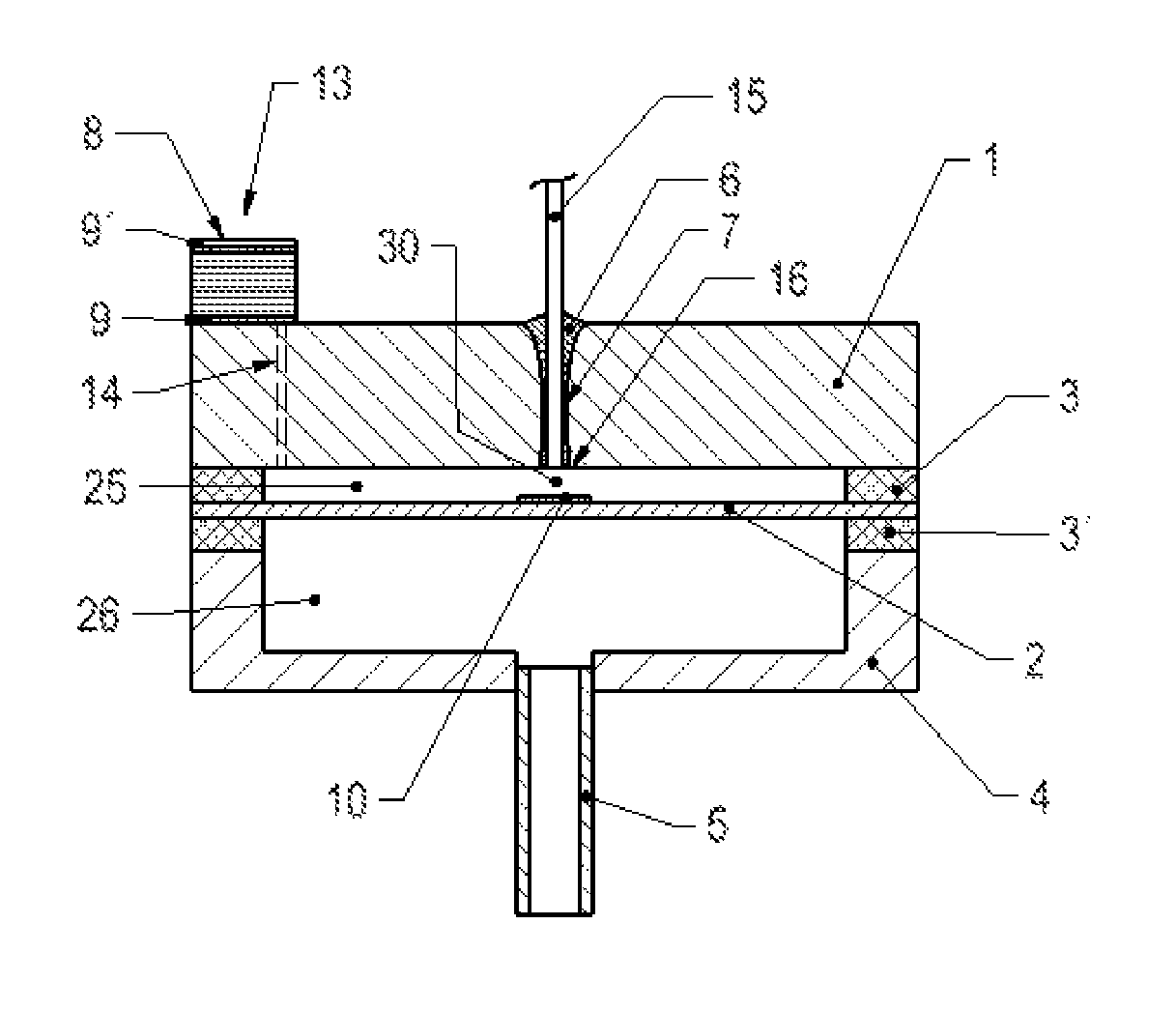
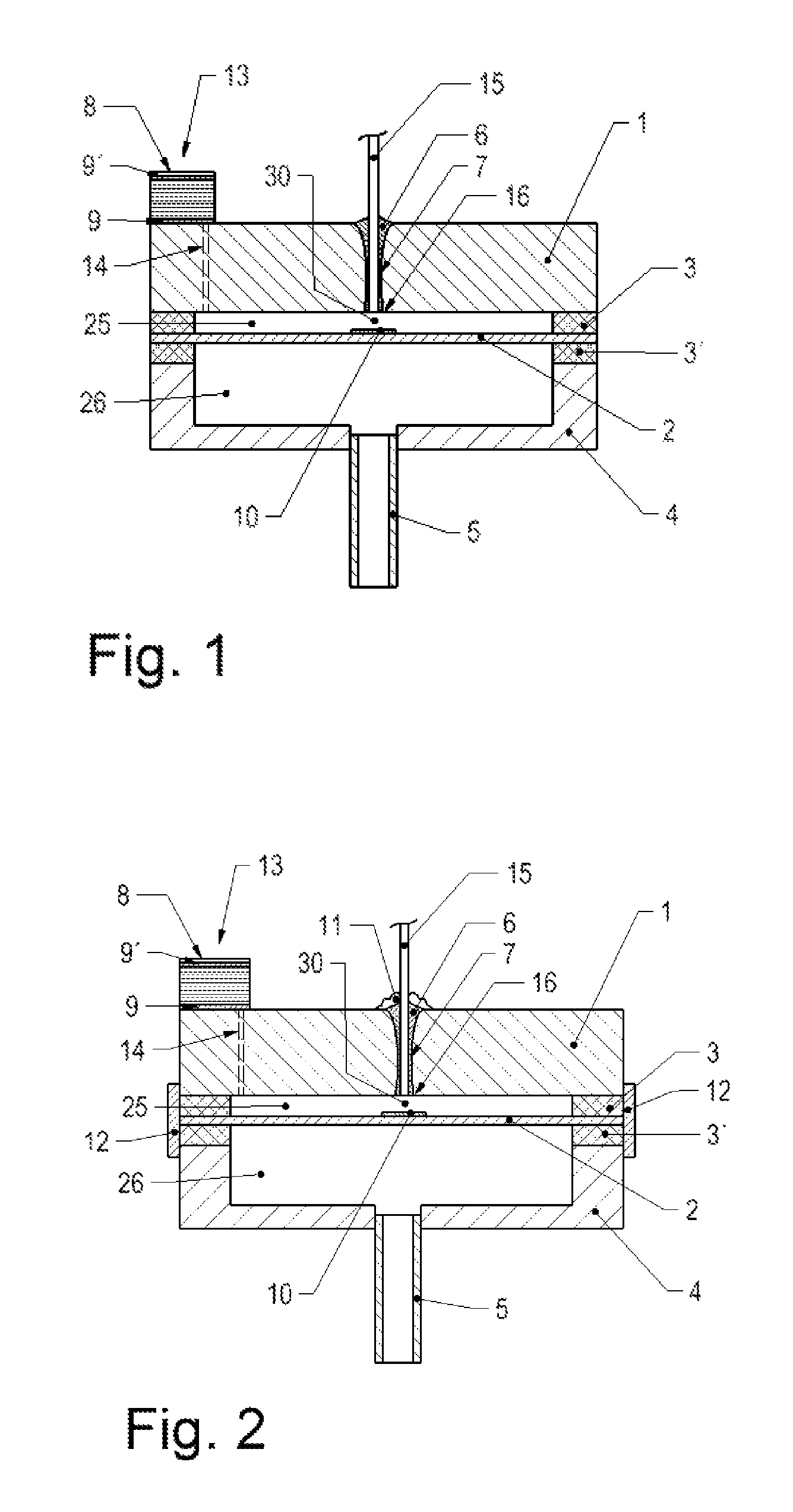
[0042]The preferred inventive arrangement of an ODG (Optical Diaphragm Measuring Cell) measuring cell made of Al2O3 with a structure essentially symmetrical about the membrane 2 is illustrated by the cross-section in FIG. 1. The first housing 1 body consists of a ceramic plate made of Al2O3 which along its edges is tightly bonded at a distance of 5 μm to 80 μm relative to the ceramic membrane 2 and which encloses a reference pressure chamber 25 which is preferably a vacuum chamber. The distance between the two surfaces is usually established directly during the assembly by means of the sealing material 3, 3′ located between the membrane edge and the housing. In this way a completely plane housing plate 1 can be used. In the same way a measurement pressure chamber 26 is formed in a second housing body 4 on the opposite membrane side; this pressure chamber is accessible for the media to be measured via a connecting port 5 through an opening in the housing 4. The cell arrangement is es...


PUM

PropertyMeasurementUnit
temperaturesaaaaaaaaaa
thicknessaaaaaaaaaa

Abstract

A pressure measuring cell has a first housing body and a membrane arranged proximate the housing body, both of ceramic. The membrane has a peripheral edge joined to the first housing body to create a reference pressure chamber. A second housing body made of ceramic material is opposite the membrane and is joined to the peripheral edge of the membrane, the second housing body together with the membrane forming a measurement pressure chamber. The second housing body has a port for connecting the pressure measuring cell to a medium to be measured. The first housing body, the second housing body and the membrane are tightly connected along the peripheral edge of the membrane in a central area of the first housing body a hole is formed, reaching through the first housing body and at least in the central region of the membrane and opposite the hole a surface of the membrane is formed as a first optically reflective area. An optical fiber is arranged and tightly fixed within the hole for feeding light onto the surface of the membrane. The end of the fiber reaches at least the surface of the first housing body and is formed as a second reflective optical area linking the surface so that between the fiber end and the reflection area an optical cavity is present which forms a measuring section for determining the level of deflection of the membrane and which is part of a Fabry-Perot Interferometer.

Description

FIELD OF THE INVENTION[0001]The invention relates to an optical diaphragm gauge for measuring high vacuum pressure in a wide pressure range.DESCRIPTION OF THE RELATED ART[0002]It is known that pressures or pressure differences can be measured by applying pressure to a thin membrane and measuring its deflection. A known and suitable method for measuring the deflection is to design the membrane arrangement as a variable electrical capacitance where the capacitance change which correlates with the pressure change is evaluated by measurement electronics in a known manner. The capacitance is created by arranging a thin, flexible membrane very close to another surface and by depositing an electrically conductive film on both mutually opposed surfaces or by fabricating them from electrically conductive material. When pressure is applied to the membrane the deflection changes the distance between the two electrodes which leads to an analyzable capacitance change of the arrangement. Sensors ...

Claims


Application Information

Patent Timeline
Patent Type & Authority Patents(United States)
IPC IPC(8): G01L9/12
CPCC04B37/005G01L9/0079C04B2237/064C04B2237/10C04B2237/343Y10T29/49776C04B2237/74Y10T29/49002C04B2237/704
Inventor ANTILA, JARKKOBERTSCH, DIETMARMULLIS, FELIXWUEST, MARTIN
Owner INFICON HLDG AG
Learn More