Rack-level power management of computer systems

a computer system and power management technology, applied in the direction of instruments, liquid/fluent solid measurement, electrical apparatus casings/cabinets/drawers, etc., can solve the problem of power consumption data transmission

Active Publication Date: 2010-04-27
HEWLETT-PACKARD ENTERPRISE DEV LP
View PDF16 Cites 19 Cited by
  • Summary
  • Abstract
  • Description
  • Claims
  • Application Information

AI Technical Summary

Problems solved by technology

The resultant power consumption data is transmitted from each computer in the group to a centralized power manager.

Method used


Image

  • Rack-level power management of computer systems
  • Rack-level power management of computer systems
  • Rack-level power management of computer systems

Examples


Embodiment Construction

[0016]As discussed above, server racks and similar systems require substantial power to operate, and continuous operation of the servers is of critical importance in data centers, compute farms, and other applications. Recently, high-density computing systems, for example implemented using blade servers, are becoming more prevalent. Applicants have found that such high-density computing racks may have power requirements beyond what the older infrastructure of the data centers was designed to accommodate.

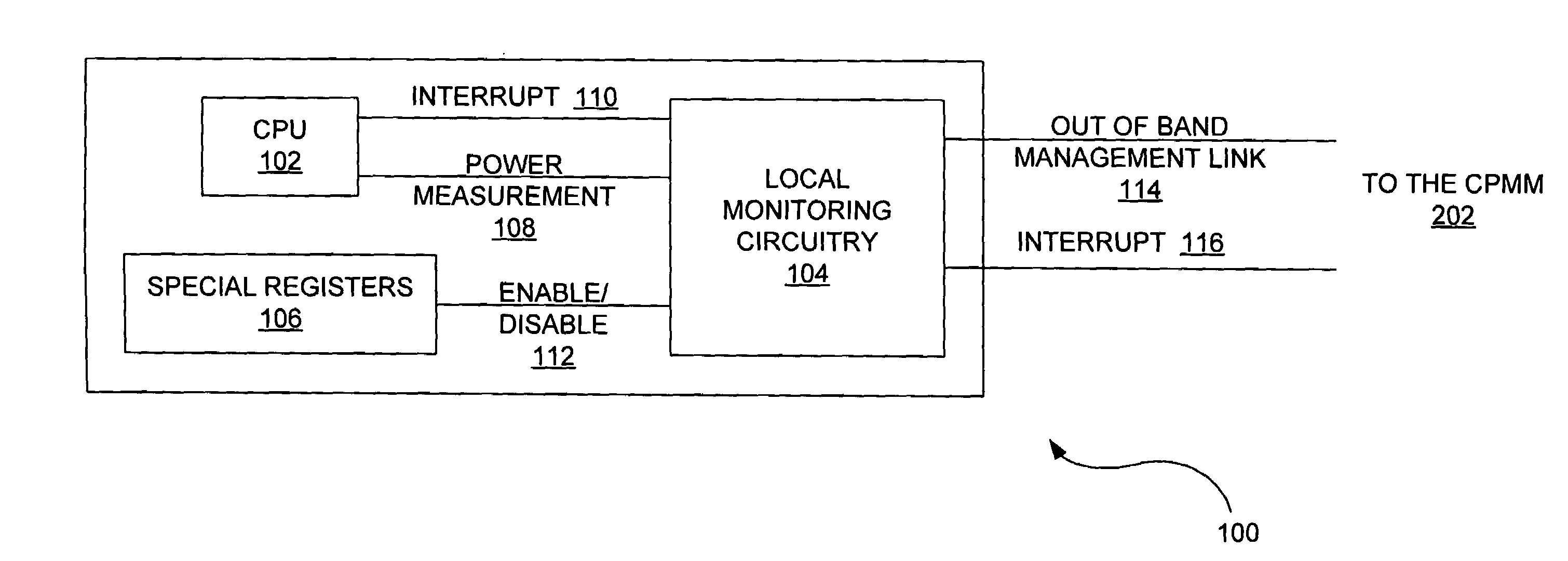
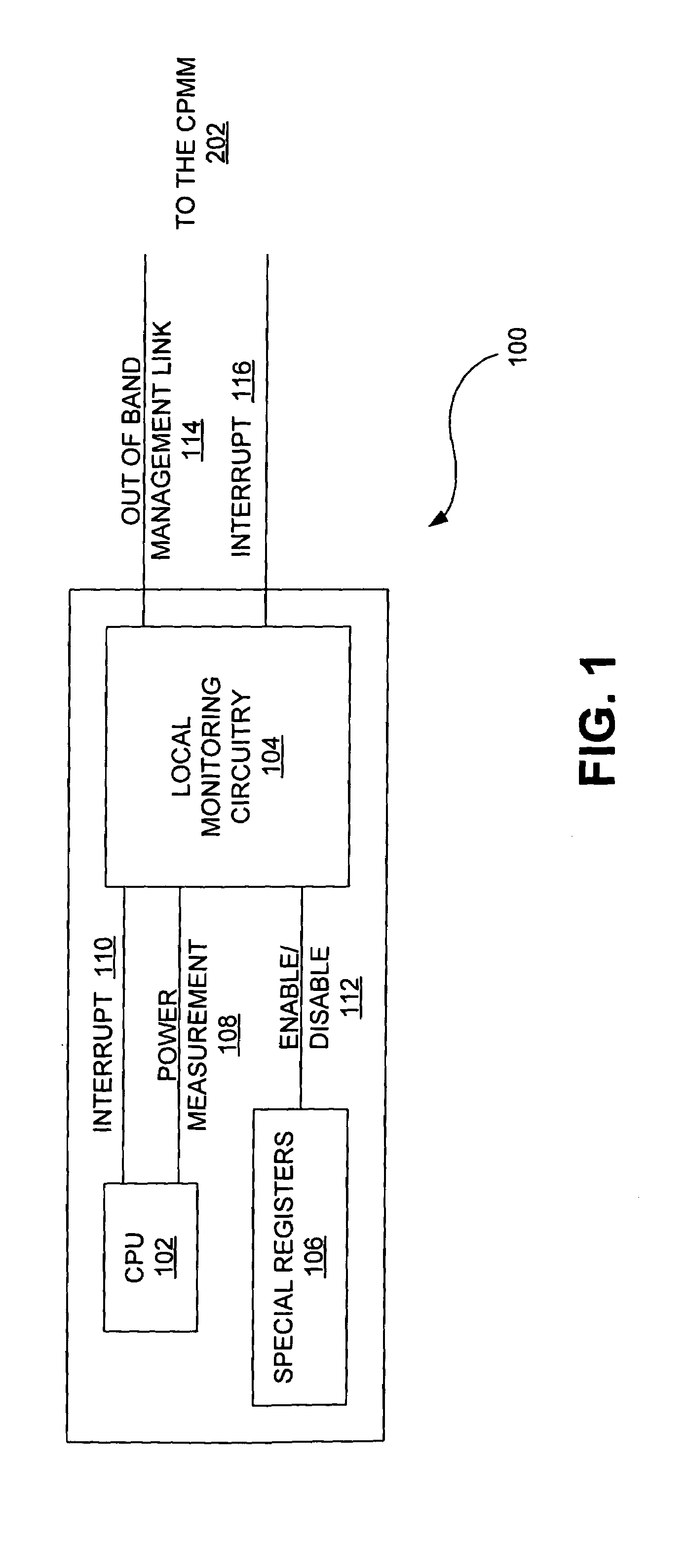
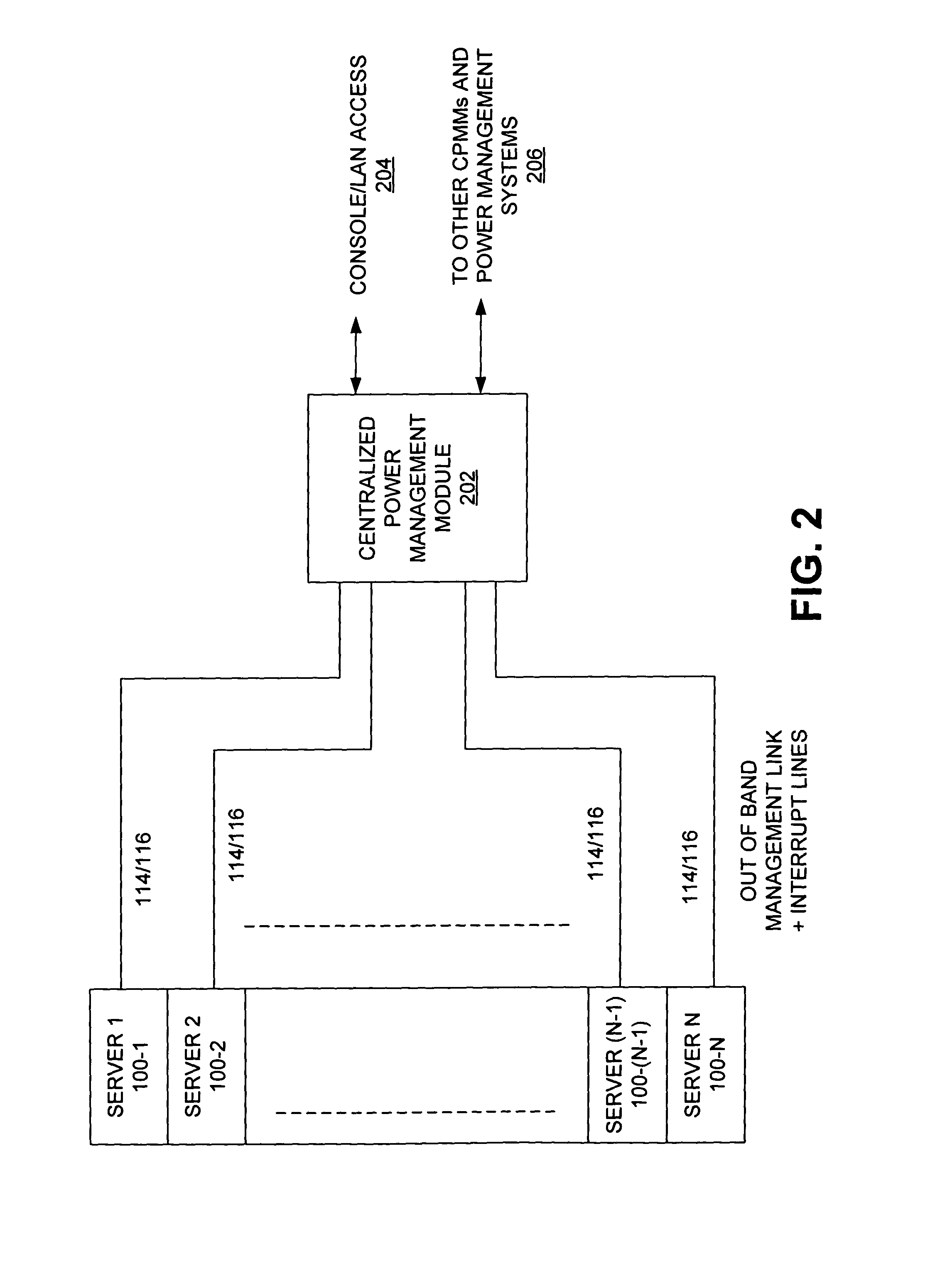
[0017]To overcome this problem, a policing mechanism may be used to enable using these new higher-wattage servers in existing data centers or compute farms. One embodiment of the present invention targets for policing the parts of the system with the highest power consumption, those parts being the central processing units (CPUs) of the servers. Another embodiment employs a CPMM to track power utilization over time, and uses this information in conjunction with other parameters (for ...


PUM


Abstract

One embodiment disclosed relates to a system for power management of a group of computers. The system includes server side infrastructure (SSI) circuitry at each computer in the group and a centralized power management module (CPMM). The SSI circuitry includes local monitoring circuitry coupled to a central processing unit (CPU) of the computer. The CPMM has a management link to the SSI circuitry at each computer in the group. The local circuitry at each computer monitors power consumption at the CPU of that computer and transmits power consumption data to the CPMM. The CPMM applies a set of rules to the power consumption data to determine when and at which computers to enable and disable a CPU power throttling mode.

Description

BACKGROUND OF THE INVENTION[0001]1. Field of the Invention[0002]The present invention relates generally to power supplies for electronics and computers.[0003]2. Description of the Background Art[0004]Computer networks, such as the Internet, utilize high performance computer systems called “servers.” Servers typically have high performance processors and contain hardware and software capable of handling large amounts of data. Servers provide a large number of computer users with compute services and access to large stores of information. For example, servers are used to host web sites that can be accessed by many computers via the Internet.[0005]Multiple server components are often housed within a server housing or “server rack”. Server racks are typically box-like structures or cabinets that contain a number of removable electronic modules or electronic trays. Each electronic tray can be a different server, or each electronic tray can hold one or more components of a server.[0006]Ot...

Claims


Application Information

Patent Timeline
Patent Type & Authority Patents(United States)
IPC IPC(8): G06F1/32G06F1/28
CPCG06F1/3203
Inventor CHHEDA, SACHIN NAVINKOEHLER, LOREN M.DOBBS, ROBERT WILLIAM
Owner HEWLETT-PACKARD ENTERPRISE DEV LP
Why Eureka
Try Eureka