
Radiation detector with extended dynamic range

a technology of dynamic range and radiation detector, which is applied in the direction of radiation control devices, optical radiation measurement, instruments, etc., can solve the problems of the final sensitivity and dynamic range of the instrument whose transduction mechanism is the optical readout of an array of mems micro mirrors, and achieve a larger dynamic temperature sensing range, improved dynamic range, and increased conventional dynamic range

Inactive Publication Date: 2010-04-27
FLIR COMML SYST
View PDF6 Cites 27 Cited by
  • Summary
  • Abstract
  • Description
  • Claims
  • Application Information

AI Technical Summary

Benefits of technology

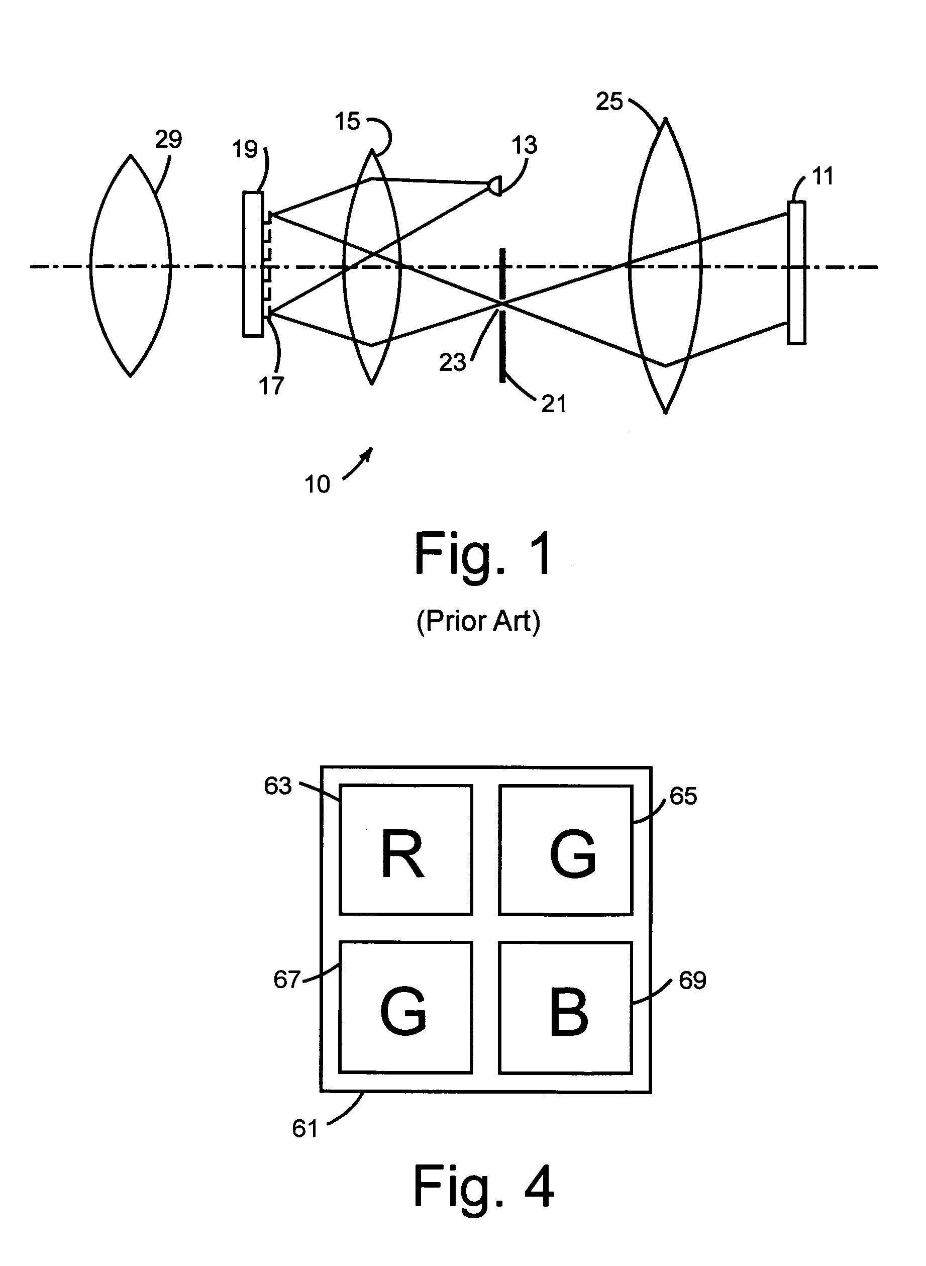
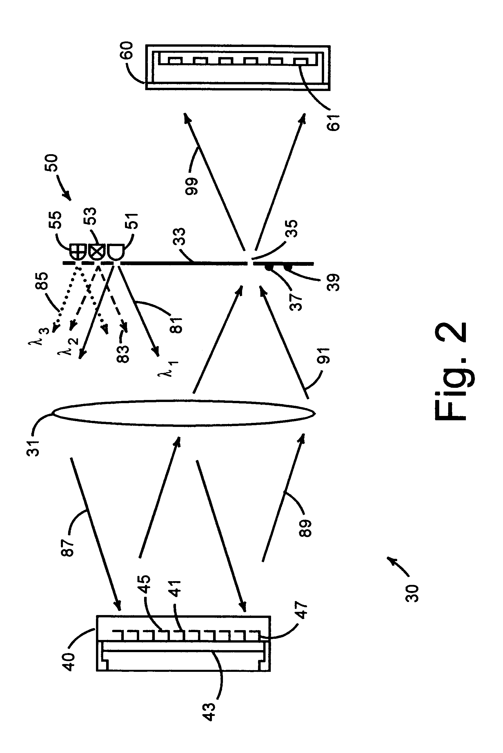
[0011]An advanced optical arrangement is disclosed to enable read out of the movements of an array of micro mirrors with improved dynamic range. The utility of this method may be applied to any array of micro mirrors whose movements and positions transduce some desired information. The present invention is related to a mechanical-optical transducer that has larger dynamic temperature sensing range than conventional devices, such as optical read-out thermal imagers. The conventional dynamic range is increased by using an optical wavelength multiplexing technique. Optical multiplexing is generally unique to optical systems, in which the dynamic range is multiply-increased by means of using multiple read-out light sources that are distinguishable in the read-out section. The method for such distinguishable means include use of light beams of different wavelengths, different modulations, and different polarizations. Exemplary embodiments of the present invention include the following implementations.

Problems solved by technology

In all such cases, the ultimate sensitivity and dynamic range of an instrument whose transduction mechanism is the optical readout of an array of MEMS micro mirrors is at issue.

Method used


Image

  • Radiation detector with extended dynamic range
  • Radiation detector with extended dynamic range
  • Radiation detector with extended dynamic range

Examples


Embodiment Construction

[0031]The following detailed description is of the best currently contemplated modes of carrying out the invention. The description is not to be taken in a limiting sense, but is made merely for the purpose of illustrating the general principles of the invention, since the scope of the invention is best defined by the appended claims. In an exemplary embodiment, the disclosed device and method are applicable to the use of an array of micro mirrors in a thermal imaging camera.

[0032]The present invention is related to a mechanical-optical transducer readout device that can provide a larger dynamic response than that of conventional MEMS devices. This performance feature is highly desirable in, for example, radiation detection or thermograph applications such as fire fighting. In radiation detectors used for fire fighting applications, there is a need for a dynamic range that may exceed 400 C.°. In a conventional detection system, such a range may be obtainable, but only if detection s...


PUM


Abstract

A mechanical-optical transducer comprises a readout illumination source providing light having different wavelengths or different polarization states; an image sensor array for sensing the light from the readout illumination source; and a mechanical-optical device including sensing pixels whose optical property change in response to incident thermal infrared radiation, the mechanical-optical device having a reflective surface disposed to selectively reflect light from the readout illumination source to the image sensor array.

Description

CROSS-REFERENCE TO RELATED APPLICATION[0001]The present application is a continuation-in-part of patent application Ser. No. 11 / 711,275 entitled “Thermal displacement-based radiation detector of high sensitivity,” filed 27 Feb. 2007.BACKGROUND OF THE INVENTION[0002]1. Field of Invention[0003]The present invention relates to arrays of micro mirrors structured by MEMS (micro electrical mechanical systems) and, in particular, to radiation detection devices using optical readout of micro mirror orientations.[0004]2. Description of the Background Art[0005]In recent years, MEMS devices micromachined from silicon by electronics-industry techniques, have become important as transducers of various kinds. MEMS devices may be structured individually or in arrays. When a physical effect causes a microscopic deflection of a MEMS structure having a micro mirror, it is advantageous to detect the deflection with a reflected light beam. One well known example is the atomic force microscope, whereby ...

Claims


Application Information

Patent Timeline
Patent Type & Authority Patents(United States)
IPC IPC(8): H01L25/00
CPCG01J5/08G01J5/0806G01J5/40G01J5/0853G01J5/0896G01J5/0831
Inventor JIN, GUANGHAIZHANG, LEIZHAO, JING
Owner FLIR COMML SYST
Learn More