
Electrical conductor and core for an electrical conductor

a technology of electrical conductors and cores, applied in the direction of insulated conductors, power cables, cables, etc., can solve the problems of non-uniform cores, cables are susceptible to corrosion, and cables are susceptible to excessive sag

Active Publication Date: 2010-04-27
ADVANCED TECH HLDG
View PDF12 Cites 31 Cited by
  • Summary
  • Abstract
  • Description
  • Claims
  • Application Information

AI Technical Summary

Benefits of technology

The solution provides a flexible, resilient, and uniformly strong composite core that minimizes sagging and corrosion, while allowing for tailored resin systems and precise carbon fiber placement, resulting in improved performance and durability for electrical conductors.

Problems solved by technology

Amongst other drawbacks, such cables are susceptible to excessive sag in certain climates and under certain operating conditions.
Furthermore, such cables are susceptible to corrosion in other environments.
While the composite material is resistant to corrosion, and may be less susceptible to sagging, the fiber construction and the method of manufacturing same leads to non-uniform cores, which may not be of sufficient strength for a particular application.
Moreover, the placement of the carbon fiber limits the desirability of such a core.

Method used


Image

  • Electrical conductor and core for an electrical conductor
  • Electrical conductor and core for an electrical conductor
  • Electrical conductor and core for an electrical conductor

Examples


Embodiment Construction

[0037]While this invention is susceptible of embodiment in many different forms, there is shown in the drawings and described herein in detail a specific embodiment with the understanding that the present disclosure is to be considered as an exemplification of the principles of the invention and is not intended to limit the invention to the embodiment illustrated.

[0038]It will be understood that like or analogous elements and / or components, referred to herein, may be identified throughout the drawings by like reference characters. In addition, it will be understood that the drawings are merely schematic representations of the invention, and some of the components may have been distorted from actual scale for purposes of pictorial clarity.

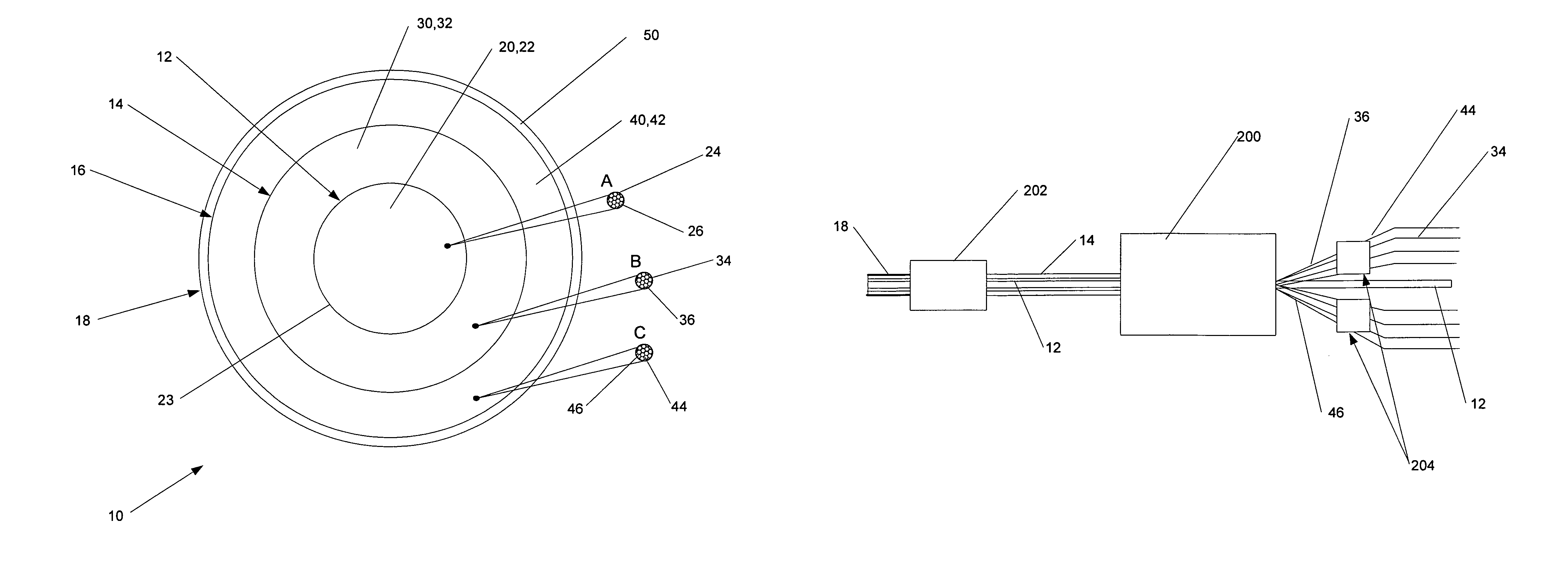
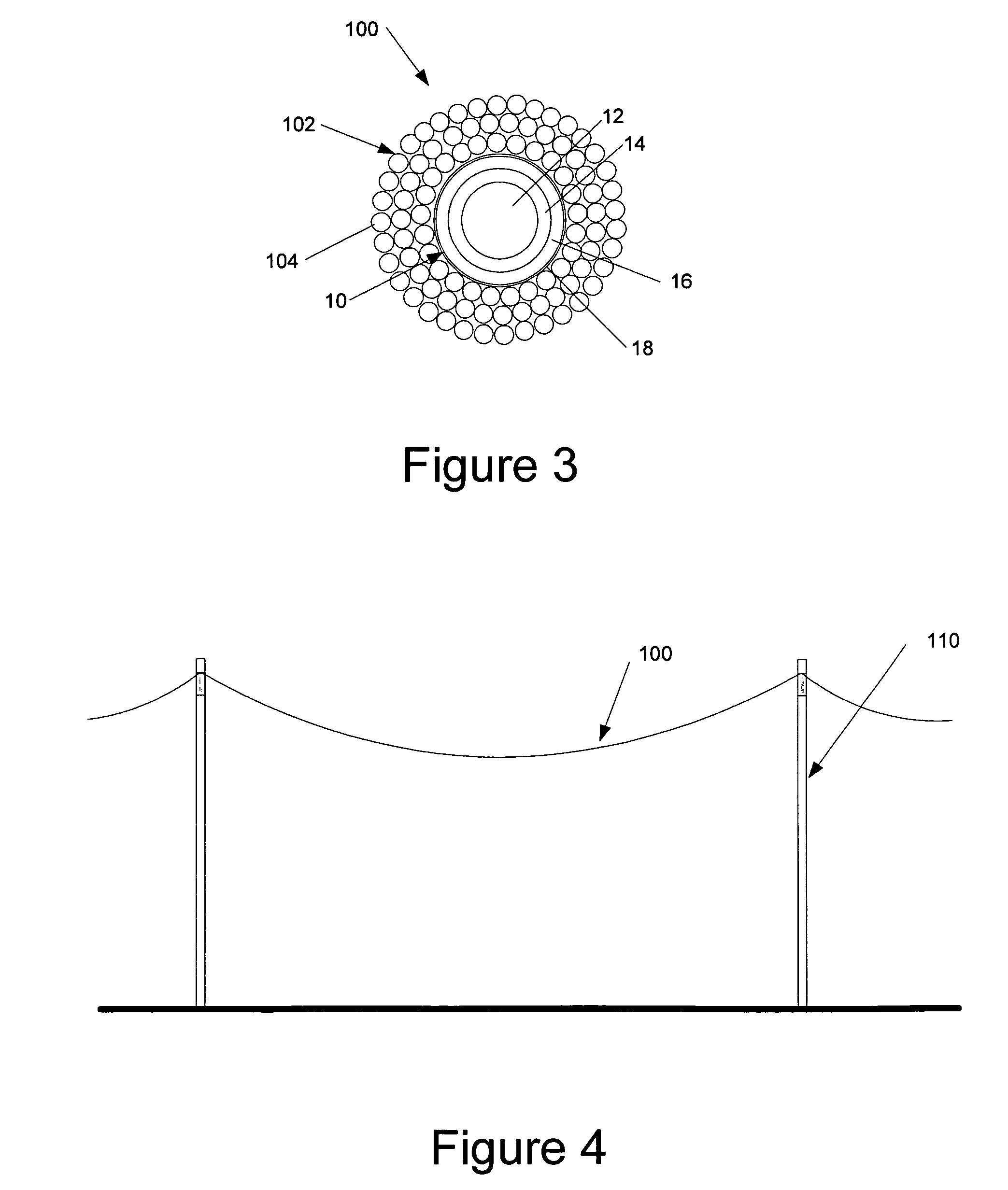
[0039]Referring now to the drawings and in particular to FIG. 3, an electrical conductor is shown at 100. The electrical conductor of the type associated with the present invention is typically referred to as stranded overhead transmission and distr...


PUM

PropertyMeasurementUnit
angleaaaaaaaaaa
angleaaaaaaaaaa
operating voltagesaaaaaaaaaa

Abstract

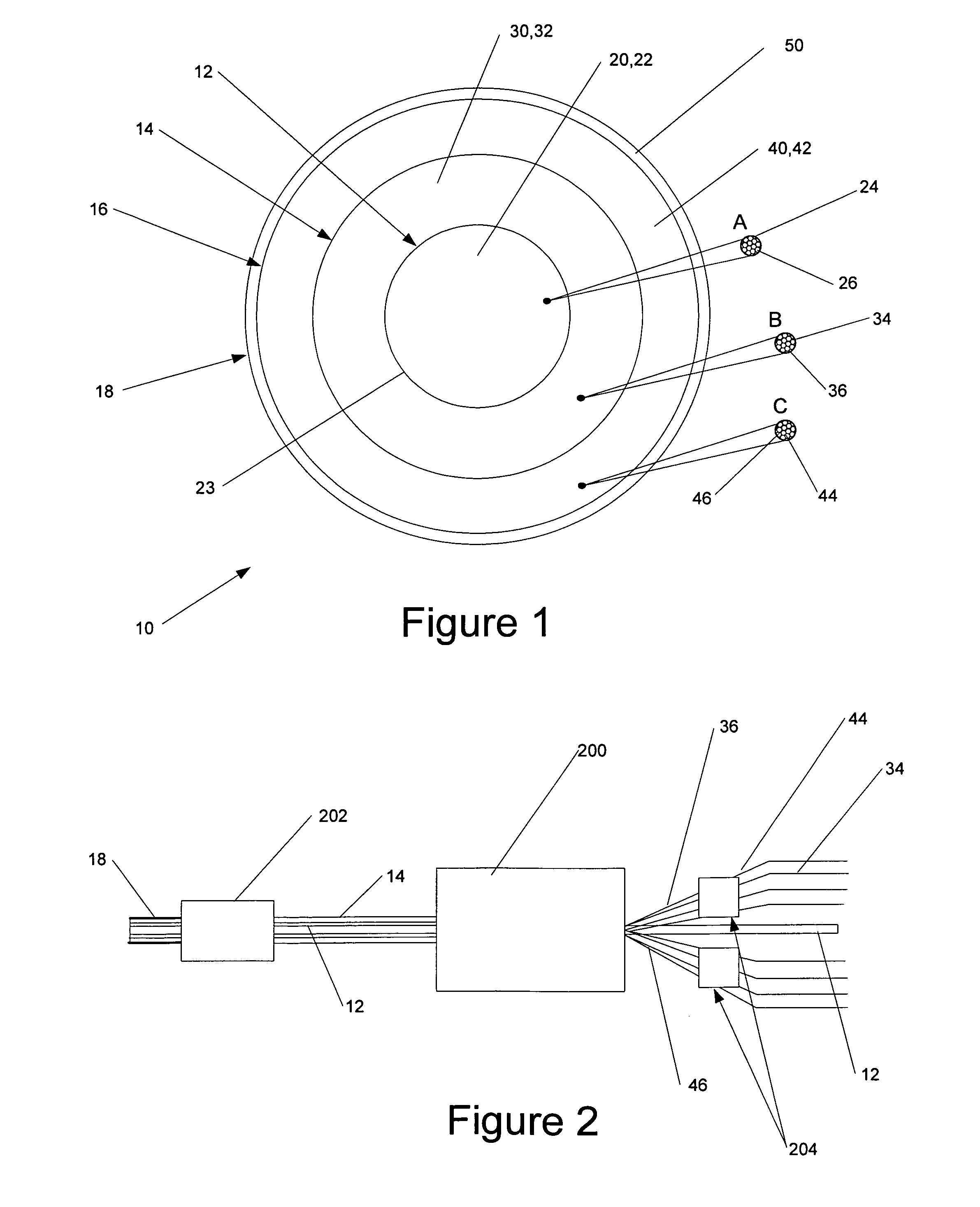
A core for an electrical conductor. The core includes an inner core component, an intermediate cladding component and an outer cladding component. The inner core component comprises a plurality of glass based stranded members in a first resin matrix. The intermediate cladding component surrounds the inner core component and comprises a plurality of carbon stranded members in a second resin matrix. The outer cladding component surrounds the intermediate cladding component and comprises a plurality of glass based stranded members in a third resin matrix. The first resin matrix and the second resin matrix are substantially independent of each other, meeting at a boundary. An electrical conductor as well as a manufacturing method is likewise disclosed.

Description

CROSS REFERENCE TO RELATED APPLICATION[0001]This application claims priority from U.S. Provisional Patent Application Ser. No. 60 / 901,404 filed Feb. 15, 2007, entitled “Electrical Conductor and Core for An Electrical Conductor” the entire specification of which is hereby incorporated by reference.BACKGROUND OF THE INVENTION[0002]1. Field of the Invention[0003]The invention relates in general to electrical transmission and distribution cables, and more particularly, to an electrical conductor having a core comprising a composite construction.[0004]2. Background Art[0005]The demand for transmission and distribution cables increases with the greater demand for electricity. As the appetite for power increases, new electrical cables continue to be installed. Additionally, to increase capacity, other electrical installations are rewired with cables of greater capacity.[0006]Traditionally, such electrical cables comprise a central stranded steel core which is wrapped in a stranded aluminum...

Claims


Application Information

Patent Timeline
Patent Type & Authority Patents(United States)
IPC IPC(8): H01B7/18
CPCH01B5/105H01B1/22B32B15/04H01B7/0009H01B9/006
Inventor WINTERHALTER, MICHAEL A.
Owner ADVANCED TECH HLDG
Learn More