
Coiled wire armored cable

a technology of armored cables and wires, applied in the direction of insulated conductors, power cables, cables, etc., can solve the problems of generating considerable noise on the conductors, damage to the field cables used in such operations, and exceeding the useful signal

Active Publication Date: 2010-04-27
AMPHENOL CORP
View PDF26 Cites 8 Cited by
  • Summary
  • Abstract
  • Description
  • Claims
  • Application Information

AI Technical Summary

Benefits of technology

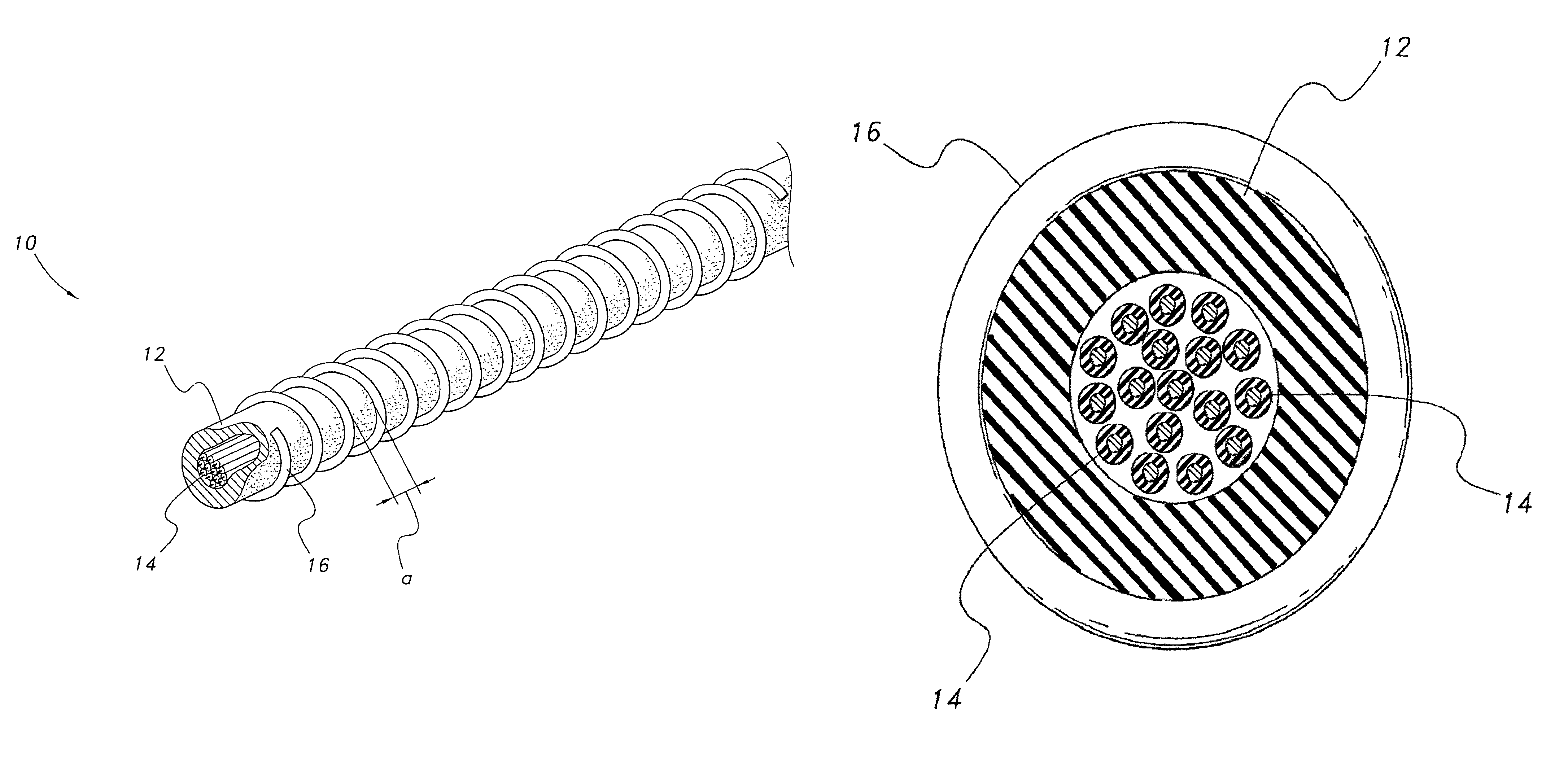
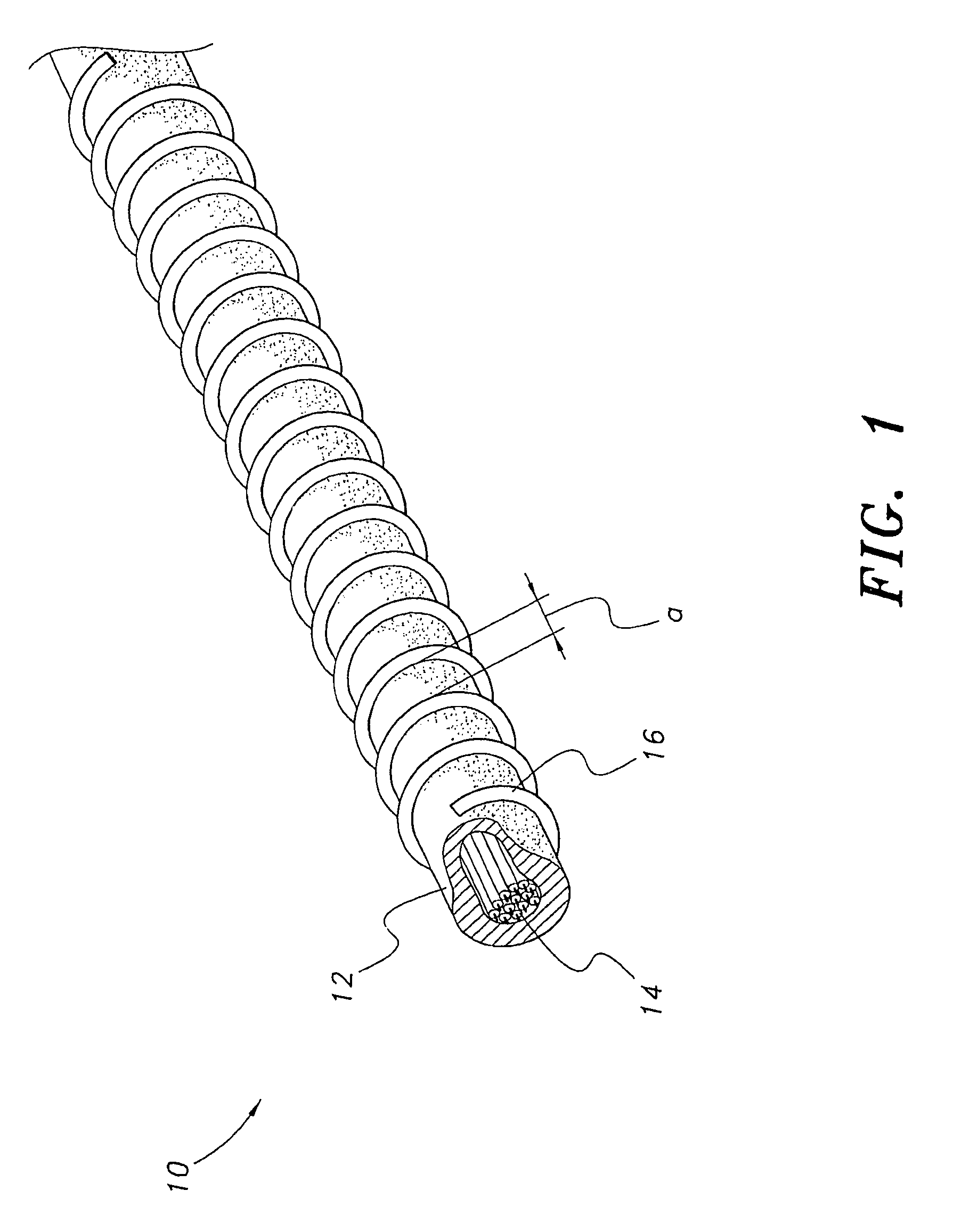
The patent describes a coiled wire armored cable used for electrical transmission. The cable has insulation material around its exterior, with a protective wire wound around it in a spiral pattern. The protective wire is made of a malleable metal and forms coils that are spaced apart along the length of the cable. This design provides protection against damage to the cable during installation and use. The technical effect of this invention is to improve the durability and reliability of coiled wire armored cables.

Problems solved by technology

Field cables used in such operations are subject to damage by rodents or other small or large animals.
In seismic operations, a high degree of insulation is required on the conductors because even minute leakages to the ground can cause considerable noise to be generated on the conductors that may even exceed the useful signals.
In the past, electrical transmission cables were usually suspended above ground in populated areas and supported by the ubiquitous, unattractive telephone pole or metal tower.
Furthermore, in outlying regions, the cost and difficulty of stringing cable over rugged terrain requires that the cable be positioned on or below ground.
The problem that occurs in each of the latter scenarios is that the cable is subject to attack by gnawing rodents i.e. mice, squirrels, gophers, etc.
The gnawing rodents often chew through the cable, thereby causing a breach in the transmission of electrical current.
This procedure is both costly and time-consuming.
Although this arrangement affords protection from gnawing rodents, it greatly increases the weight while decreasing the flexibility of the cable.
This increased weight and decreased flexibility play havoc with the cable installers' ability to transport and manipulate the cable.

Method used


Image

  • Coiled wire armored cable
  • Coiled wire armored cable
  • Coiled wire armored cable

Examples


Embodiment Construction

[0013]The present invention comprises a cable having electrical transmission wires encased by an insulator. A solid, protective wire is spirally wound over the exterior of the insulator. The protective wire is fabricated from steel or titanium material and will have a gauge that prevents a rodent from chewing therethrough. The coils of the protective wire are spaced along the length of the cable. The spacing of the coils will be less than the width of the teeth of the rodent, so that the coils create a “fence” that prevents the rodent's teeth from contacting the insulator. Because the coils are spaced, additional cable weight is minimized. The spaced coils also permit the cable to retain a high degree of flexibility so that the cable can be rolled to enhance portability.

[0014]Accordingly, the invention presents an electric cable that utilizes a shield that prevents destruction thereof by gnawing rodents. The shield is fabricated from wire and employs a spaced-apart coil design so th...


PUM

PropertyMeasurementUnit
lengthaaaaaaaaaa
widthaaaaaaaaaa
flexibleaaaaaaaaaa

Abstract

The coiled wire armored cable (10) includes transmission wires (14) encased by an insulator (12). A solid protective wire (16) is spirally wound over the exterior of the insulator. The protective wire (16) is fabricated from a metal, such as steel or titanium material, and will have a gauge that prevents a rodent from chewing through the wire. The coils of the protective wire are spaced apart along the length of the cable. The spacing (a) of the coils will be less than the width of the teeth of the rodent so that the coils create a “fence” that prevents the rodent's teeth from contacting the insulator.

Description

TECHNICAL FIELD[0001]The present invention generally relates to electrical transmission apparatus. More specifically, the present invention is drawn to an electrical cable having a wrapping that protects against rodent damage.BACKGROUND ART[0002]This invention is particularly concerned with the use of electrical cables in field operations, where often many thousands of feet of electrical cable are laid out for the conduct of seismic geophysical operations. Field cables used in such operations are subject to damage by rodents or other small or large animals. In seismic operations, a high degree of insulation is required on the conductors because even minute leakages to the ground can cause considerable noise to be generated on the conductors that may even exceed the useful signals. Thus, it is imperative that such cables be adequately protected against rodent and other animal bite damage to the conductors. It is the intent and purpose of the instant invention to prevent any conductor...

Claims


Application Information

Patent Timeline
Patent Type & Authority Patents(United States)
IPC IPC(8): H01B7/10
CPCH01B7/226H01B7/18
Inventor STEWARD, JR., BILLY J.STEWARD, JOHN B.
Owner AMPHENOL CORP
Learn More