
Exhaust system of outboard motor

a technology of exhaust gas purification system and outboard motor, which is applied in the direction of steam power plants, marine propulsion, vessel construction, etc., can solve the problems of increasing the size of the entire outboard motor and the difficulty of manufacturing such a carrier, so as to improve the purification performance of exhaust gas and reduce the size of the engine

Active Publication Date: 2010-04-27
SUZUKI MOTOR CORP
View PDF7 Cites 19 Cited by
  • Summary
  • Abstract
  • Description
  • Claims
  • Application Information

AI Technical Summary

Benefits of technology

The design enhances exhaust gas purifying performance and reduces the overall size of the engine by effectively utilizing space and simplifying the catalyst placement, while maintaining high catalyst temperature and preventing excessive cooling.

Problems solved by technology

However, the structure which employs the spacer plate requires ensuring of a flat surface for arranging the plate, which causes a catalyst to be arranged far from the engine, resulting in an increasing of the size of the entire outboard motor.
Further, the structure which places plural catalysts in the plural exhaust pipes in different directions requires a complicated structure for holding the catalysts in the exhaust gas gathering member.
Therefore, it is difficult to manufacture such a carrier.

Method used


Image

  • Exhaust system of outboard motor
  • Exhaust system of outboard motor
  • Exhaust system of outboard motor

Examples


first embodiment

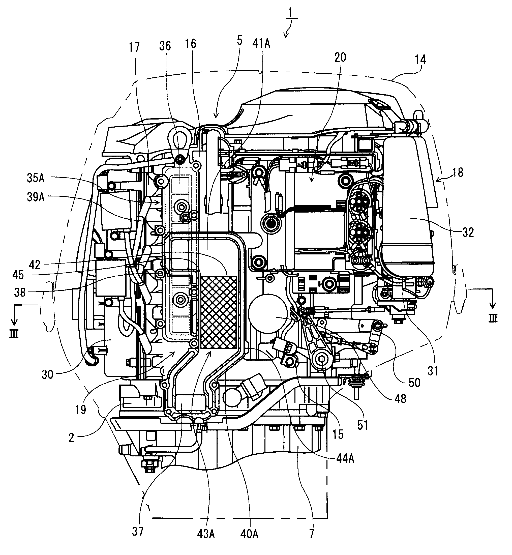
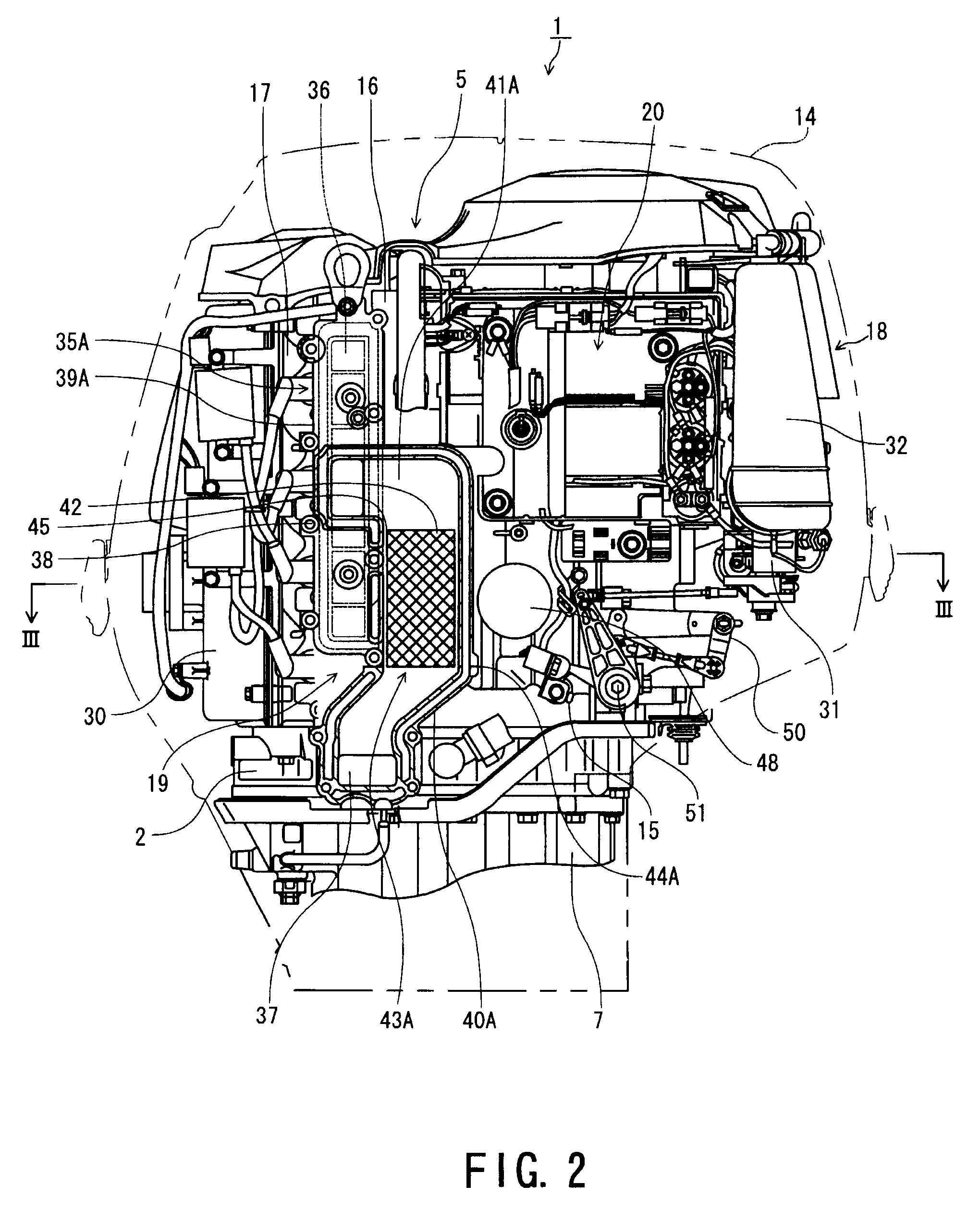
[0038]FIG. 2 is an enlarged schematic right side view illustrating the portion of the engine 5 in the outboard motor 1 according to the present invention, in which only the engine cover 14 is illustrated with an imaginary line, and FIG. 3 is a cross-sectional view taken along the line III-III in FIG. 2.

second embodiment

[0039]FIG. 4 is an enlarged schematic right side view illustrating the portion of the engine 5 in the outboard motor 1 according to the present invention, in which only the engine cover 14 is illustrated with an imaginary line, and FIG. 5 is a cross-sectional view taken along the line V-V in FIG. 4. Further, in both the embodiments) like reference numerals designate the same components.

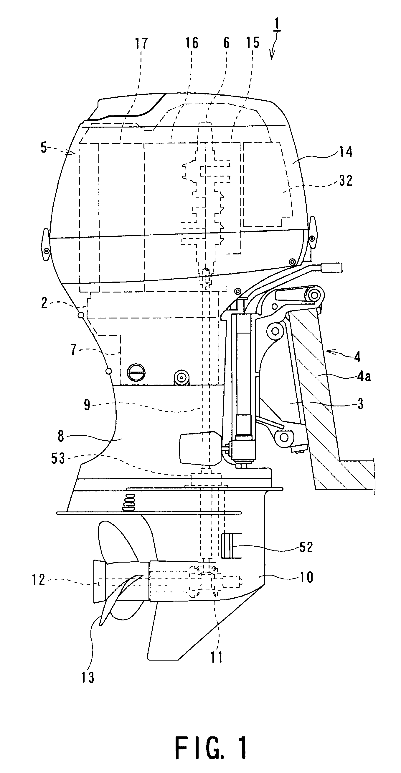
[0040]As illustrated in FIGS. 2 to 5, an intake system 18, an exhaust system 19, electrical components 20 and the like are arranged around the engine 5. While the intake system 18 is arranged from the left of the engine 5 up to a portion in front of the engine 5, the exhaust system 19 is arranged at the right of the engine 5, and the electrical components 20 are arranged at the right of the engine 5 similarly to the exhaust system 19.

[0041]Although not illustrated in detail, a plurality of cylinders 21, which are four cylinders 21 in the present embodiment, are longitudinally oriented and vertically p...


PUM


Abstract

An outboard motor includes a multi-cylinder engine which includes cylinders longitudinally oriented and vertically paralleled in a cylinder block, a cylinder head arranged at a rearward position of the cylinder blocks, and a crankcase arranged at a forward position of the cylinder block, the cylinder head having an outlet of an exhaust port at one side thereof. An exhaust system for the outboard motor includes an exhaust manifold which communicates the outlet of the exhaust port with an exhaust outlet opening, the exhaust manifold including a first exhaust gas passage extending in a vertical direction for gathering exhaust gas discharged from the outlet of each exhaust port and a second exhaust gas passage extending in a vertical direction adjacently to the first exhaust gas passage, and a catalyst unit is provided on the way of the second exhaust gas passage.

Description

CROSS-REFERENCE TO RELATED APPLICATIONS[0001]This application is a U.S. Application based upon and claiming the benefit of priority to Japanese Patent Application Japan 2007-001464 filed on Jan. 9, 2007, the contents of which are incorporated herein by reference.BACKGROUND OF THE INVENTION[0002]1. Field of the Invention[0003]The present invention relates to an exhaust system for an outboard motor.[0004]2. Related Art[0005]An internal combustion engines such as gasoline engine discharges an exhaust gas containing harmful components such as carbon monoxide (CO), hydrocarbon (HC), nitrogen oxide (NOx). An exhaust gas purifying device for rendering such harmful components harmless is generally classified into two types of devices based on their concepts.[0006]An exhaust gas purifying device of one of these types is a device which induces complete combustion of fuel in a combustion chamber of an engine for preventing generation of harmful components. An exhaust gas purifying device of th...

Claims


Application Information

Patent Timeline
Patent Type & Authority Patents(United States)
IPC IPC(8): B63H21/00F01N1/08F01N13/00F01N3/04F01N3/38B63H21/10B63H21/32B63H21/34B63H21/38F01N13/10
CPCF01N3/10B63B2770/00F01N2590/021F01N2230/04B63H20/24
Inventor ITO, JUNYOSHIOKA, HIDEHIKONAOSHIMA, TAKAYUKIKIMATA, FUMIKAZUACHIWA, TETSUSHITAKEWAKI, HIROMICHI
Owner SUZUKI MOTOR CORP
Learn More