
Color tunable light source

a color tunable light source and color tunable technology, applied in the direction of light source semiconductor devices, lighting and heating devices, instruments, etc., can solve the problem of complex driver circuitry required to operate these sources, and achieve the effect of improving the color uniformity of output light and increasing the intensity of light outpu

Active Publication Date: 2010-04-27
INTEMATIX
View PDF12 Cites 102 Cited by
  • Summary
  • Abstract
  • Description
  • Claims
  • Application Information

AI Technical Summary

Benefits of technology

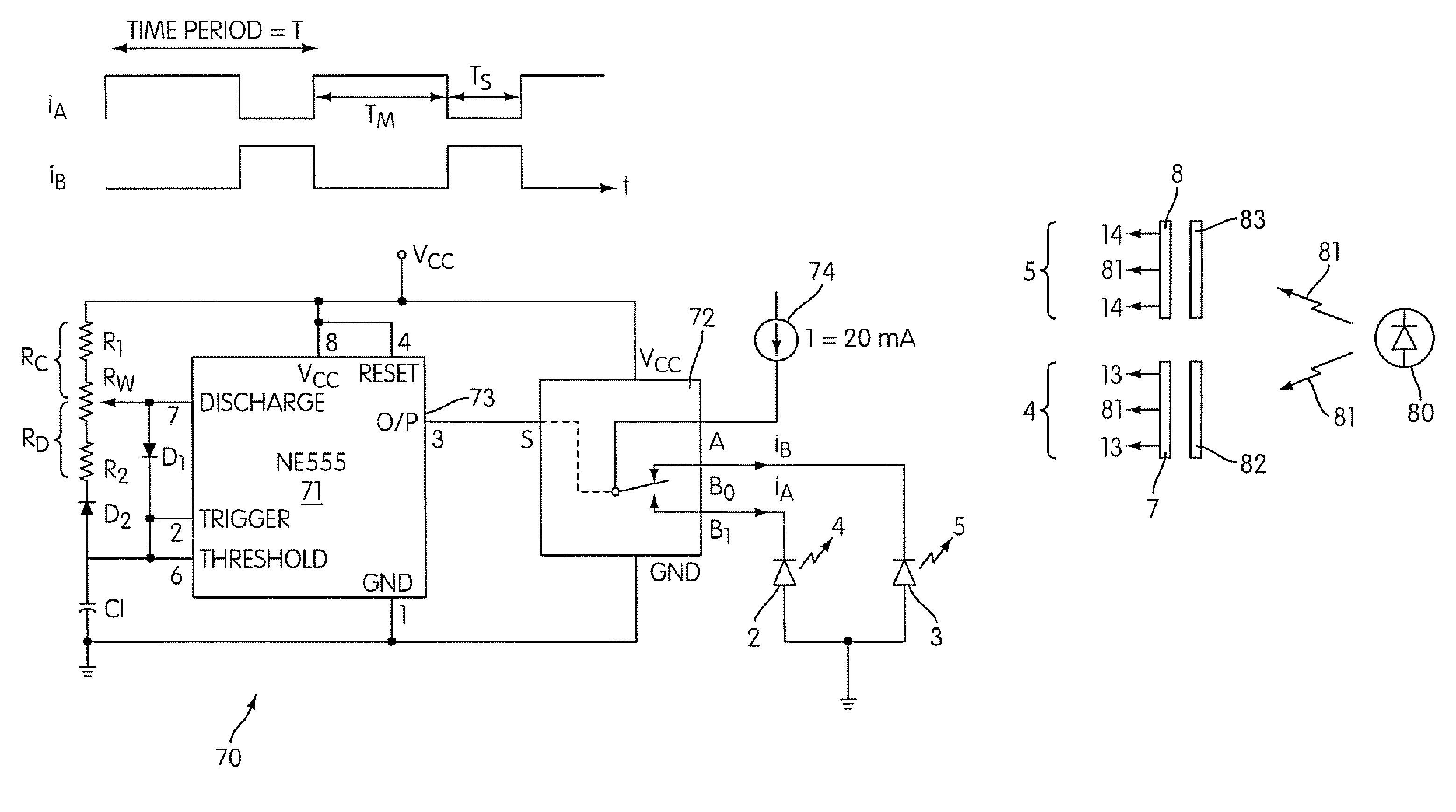
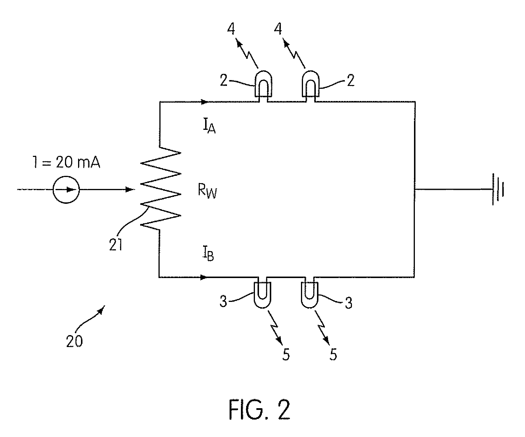
[0011]The color can be tuned by controlling the relative magnitudes of the drive currents of the LEDs using for example a potential divider arrangement. Alternatively, the drive currents of the LEDs can be switched dynamically and the color tuned by controlling a duty cycle of the drive current to control the relative proportion of time each LED emits light. In such an arrangement the controls means can comprise a pulse width modulated (PWM) power supply that is operable to generate a PWM drive current whose duty cycle is used to select a desired color. Preferably, the LEDs are driven on opposite phases of the PWM drive current. A particular advantage of the invention resides in the use of only two LED arrangements since this enables the color to be tuned by relative control of the drive currents which can be readily implemented using relatively simple and inexpensive drive circuitry.
[0012]In a further arrangement the phosphors share a common LED to provide excitation energy for the two phosphors and a respective light controller, such as a liquid crystal shutter, is associated with each phosphor. In such an arrangement the control means is operable to select the color by controlling the light controller to control the relative irradiation of the phosphors rather than controlling the LED drive current. In one such arrangement, the control means is operable to select the color by controlling the relative drive voltages of the respective light controllers to control the intensity of the excitation energy reaching its associated phosphor. Alternatively, the control means can be operable to dynamically switch the drive voltage of the light controllers and wherein the color is tunable by controlling a duty cycle of the voltage. Preferably, the control means comprises a pulse width modulated power supply operable to generate a pulse width modulated drive voltage.
[0013]In any arrangement of the invention and to increase the intensity of the light output, the light source can comprise a plurality of first and second LED arrangements that are advantageously configured in the form of an array, for example a square array, to improve color uniformity of the output light.
[0014]According to the invention a method of generating light with a selected color comprises: providing a first light emitting diode arrangement and operating it to emit light of a first color and providing a second light emitting diode arrangement and operating it to emit light of a second color; the method being characterized by the first LED arrangement comprising a phosphor provided remote to an associated first LED operable to generate excitation energy of a selected wavelength range and to irradiate the phosphor such that it emits light of a different color wherein light emitted by the first LED arrangement comprises the combined light from the first LED and the light emitted from the phosphor and controlling color of generated light by controlling the relative light outputs of the two LED arrangements.
[0015]As with the light source in accordance with the invention, the second LED arrangement can also comprise a respective phosphor provided remote to an associated second LED operable to generate excitation energy of a selected wavelength range and to irradiate the phosphor such that each emits light of a color, wherein the light emitted by the second LED arrangement comprises the combined light from the second LED and the light emitted from the phosphor and comprising selecting a color by controlling relative irradiation of the phosphors.
[0016]The method further comprises selecting a color by controlling the relative magnitude of the drive currents of the respective LEDs or dynamically switching the drive currents and selecting the color by controlling a duty cycle of a PWM drive current.

Problems solved by technology

A disadvantage of such light sources is the complexity of driver circuitry required to operate these sources.

Method used


Image

  • Color tunable light source
  • Color tunable light source
  • Color tunable light source

Examples


Embodiment Construction

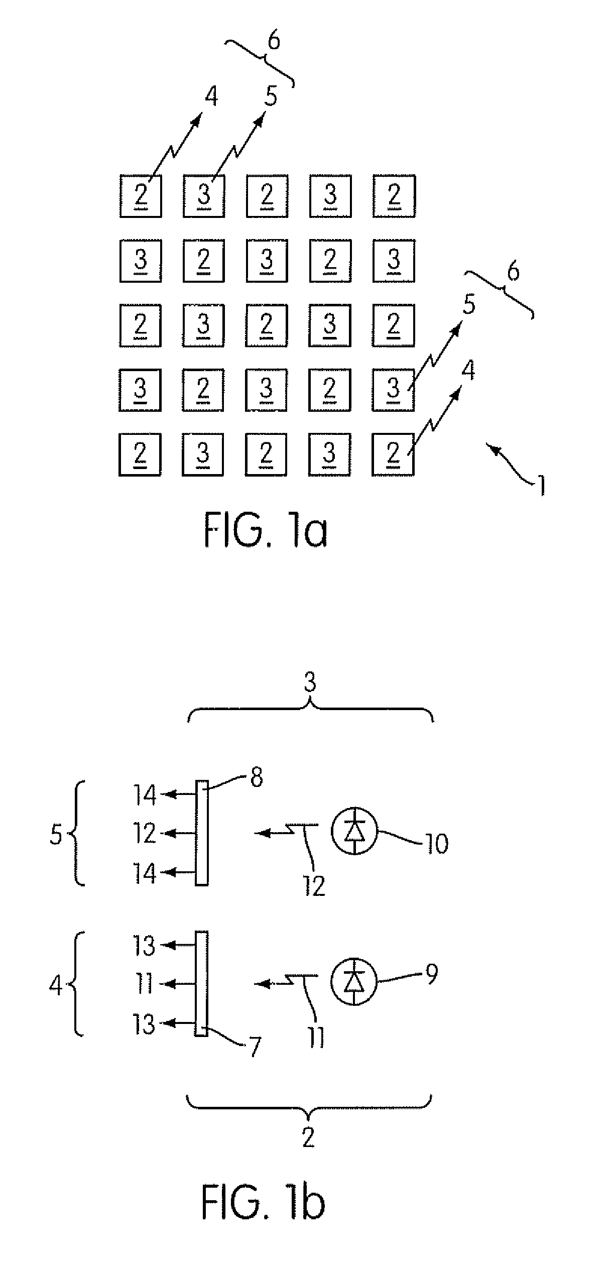
[0029]Referring to FIG. 1(a) there is shown a schematic representation of a color tunable (selectable) light source 1 in accordance with the invention that comprises an array of first light emitting diode (LED) arrangements 2 and second LED arrangements 3. In the example the array comprises a regular square array of twenty five LED arrangements with thirteen first and twelve second LED arrangements. It will be appreciated that the invention is not limited to a particular number of LED arrangements or a particular geometric layout.

[0030]Each of the first LED arrangements 2 is operable to emit light of a first color (wavelength range) and each of the second LED arrangements 3 is operable to emit light of a second color (wavelength range). In the context of this patent application light is defined as electromagnetic radiation in the visible part of the spectrum that is 400 to 750 nm. The combined light 4 and 5 emitted by the LED arrangements 2, 3 comprises the light output 6 of the sou...


PUM


Abstract

A color tunable light source comprises: a first light emitting diode (LED) arrangement operable to emit light of a first color and a second LED arrangement operable to emit light of a second color, the combined light output comprising the output of the source. One or both LED arrangements comprises a phosphor provided remote to an associated LED operable to generate excitation energy of a selected wavelength range and to irradiate the phosphor such that it emits light of a different color wherein light emitted by the LED arrangement comprises the combined light from the LED and phosphor and control means operable to control the color by controlling the relative light outputs of the two LED arrangements. The color can be controlled by controlling the relative magnitude of the drive currents of the LEDs or by controlling a duty cycle of PWM drive current.

Description

BACKGROUND OF THE INVENTION[0001]1. Field of the Invention[0002]This invention relates to a color tunable light source and in particular to a light source based on a light emitting diode (LED) arrangement. Moreover the invention provides a method of generating light of a selected color.[0003]2. Description of the Related Art[0004]Currently, the color of light generated by a light source, in particular light emitting diodes (LEDs), is determined by the physical mechanism used to generate the light. For example, many LEDs incorporate one or more phosphor materials, that is photo luminescent materials, which absorb a portion of the radiation emitted by the LED chip / die and re-emit radiation of a different color (wavelength). The color of light generated by such LEDs is the combined light from the LED chip and Phosphor which is fixed and determined when the LED is fabricated.[0005]It is also known to use a color filter with incandescent, fluorescent and other light sources to generate a...

Claims


Application Information

Patent Timeline
Patent Type & Authority Patents(United States)
IPC IPC(8): F21V9/00H05B44/00
CPCH05B33/086H05B33/0818F21K9/64H05B45/20F21Y2115/10F21Y2105/14H05B45/37
Inventor LI, YI-QUNDONG, YIXU, XIAOFENGCOLLIER, IAN
Owner INTEMATIX
Learn More