
High-efficient light engines using light emitting diodes

a technology of light-emitting diodes and light-emitting diodes, which is applied in the direction of display means, semiconductor devices of light sources, lighting and heating apparatus, etc., can solve the problems of decreasing the visible spectrum, less efficient, and inefficient current state of the art phosphor-convert white led (pc-led) technology

Active Publication Date: 2010-04-27
RENESSELAER POLYTECHNIC INST
View PDF146 Cites 89 Cited by
  • Summary
  • Abstract
  • Description
  • Claims
  • Application Information

AI Technical Summary

Benefits of technology

This configuration achieves a significant increase in light output and luminous efficacy, enabling a 1500-lumen package at 150 lm / W, while maintaining efficiency even at elevated temperatures.

Problems solved by technology

Due to their long operation (burn) time and low power consumption, solid state light emitting devices frequently provide a functional cost benefit, even when their initial cost is greater than that of conventional lamps.
Current state of the art phosphor-converted white LED (pc-LED) technology is inefficient in the visible spectrum.
More particularly, the LED device becomes less efficient when heated to a temperature greater than 100° C., resulting in a declining return in the visible spectrum.

Method used


Image

  • High-efficient light engines using light emitting diodes
  • High-efficient light engines using light emitting diodes
  • High-efficient light engines using light emitting diodes

Examples


Embodiment Construction

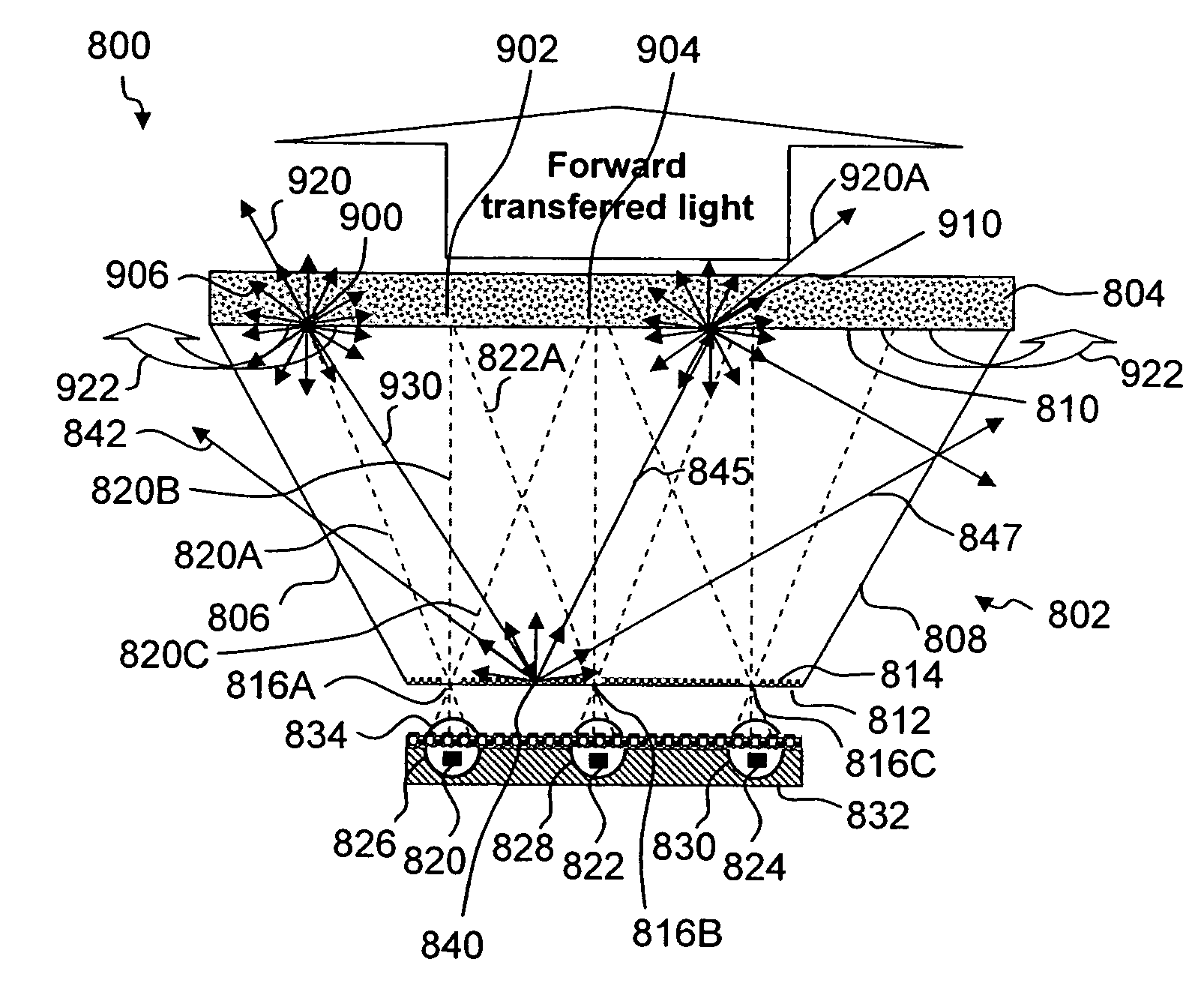
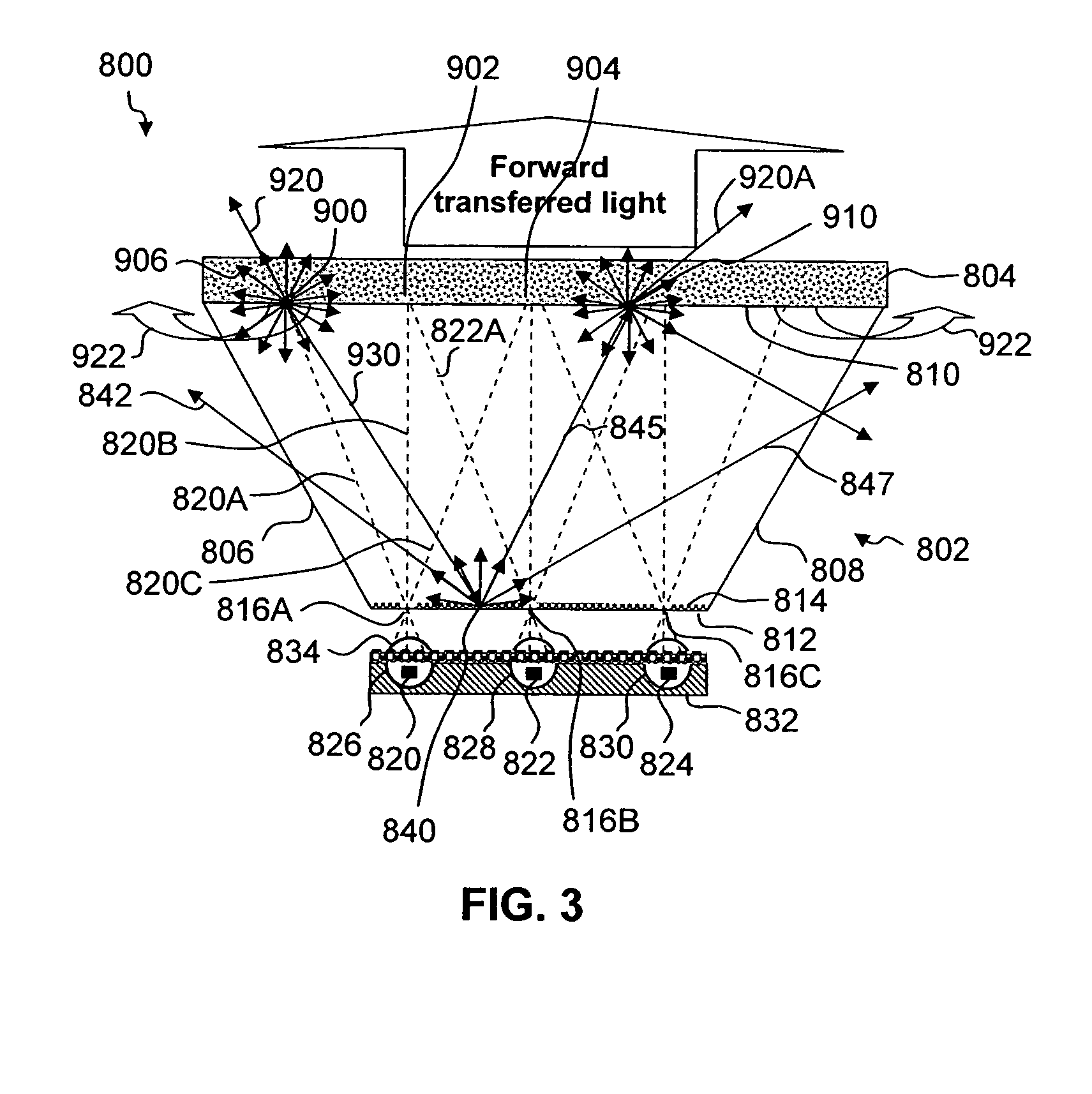
[0028]FIG. 12 is a diagram illustrating the exemplary radiation rays that may result when an exemplary radiation ray 2000 from a short-wavelength LED chip 2002 impinges on a layer of down conversion material 2004. The impingement of exemplary short-wavelength radiation 2000 from a short-wavelength source such as an LED chip 2002 onto a down conversion material layer 2004 may produce radiation with four components: back transferred short-wavelength radiation 2006 reflected from the down conversion material layer 2004; forward transferred short-wavelength radiation 2008 transmitted through the down conversion material layer 2004; forward transferred down-converted radiation 2010 transmitted through the down conversion material 2004; and back transferred down-converted radiation 2012 reflected from the down conversion material 2004. The four components may combine to produce white light.

[0029]Two of the four components 2010 and 2012 may each be comprised of two sub-components. One of t...


PUM


Abstract

A light emitting apparatus having a light source for emitting short wavelength radiation and an optic device configured to receive the radiation emitted from the light source. A device directs at least some of the short wavelength radiation emitted from the light source into the optic device and a down conversion material receives at least some of the short wavelength radiation directed into the optic device in one spectral region and emits the radiation in another spectral region.

Description

CROSS REFERENCE TO RELATED APPLICATION[0001]This application claims the benefit of priority to U.S. Provisional Application Ser. No. 60 / 841,652 filed Aug. 31, 2006, the contents of which is incorporated by reference herein.BACKGROUND OF THE INVENTION[0002]Solid state light emitting devices, including solid state lamps having light emitting diodes (LEDs), laser diodes (LDs), and resonant cavity LEDs (RCLEDs) are extremely useful, because they potentially offer lower fabrication costs and long term durability benefits over conventional incandescent and fluorescent lamps. Due to their long operation (burn) time and low power consumption, solid state light emitting devices frequently provide a functional cost benefit, even when their initial cost is greater than that of conventional lamps. Because large scale semiconductor manufacturing techniques may be used, many solid state lamps may be produced at extremely low cost.[0003]In addition to applications such as indicator lights on home ...

Claims


Application Information

Patent Timeline
Patent Type & Authority Patents(United States)
IPC IPC(8): F21V9/00H01L33/50H01L33/58H01L33/60
CPCH01L33/507H01L33/58F21K9/00H01L25/0753H01L33/60Y10S362/80H01L2933/0091H01L2924/0002H01L2924/00
Inventor NARENDRAN, NADARAJAHFREYSSINIER, JEAN PAULGU, YIMIN
Owner RENESSELAER POLYTECHNIC INST
Learn More