
Method and device for applying conductive paste

a technology of conductive paste and conductive strips, which is applied in the direction of terminal application apparatus, capacitor manufacturing, fixed capacitor details, etc., can solve the problems of disadvantageous decrease of productivity, increase time, and disadvantageous increase of protruding distances of electronic parts b>55/b> from the holding holes b>52/b> in the center portion, so as to reduce the variance of protruding distances of electronic parts, the effect of sacrificing productivity

Active Publication Date: 2010-04-20
MURATA MFG CO LTD
View PDF8 Cites 2 Cited by
  • Summary
  • Abstract
  • Description
  • Claims
  • Application Information

AI Technical Summary

Benefits of technology

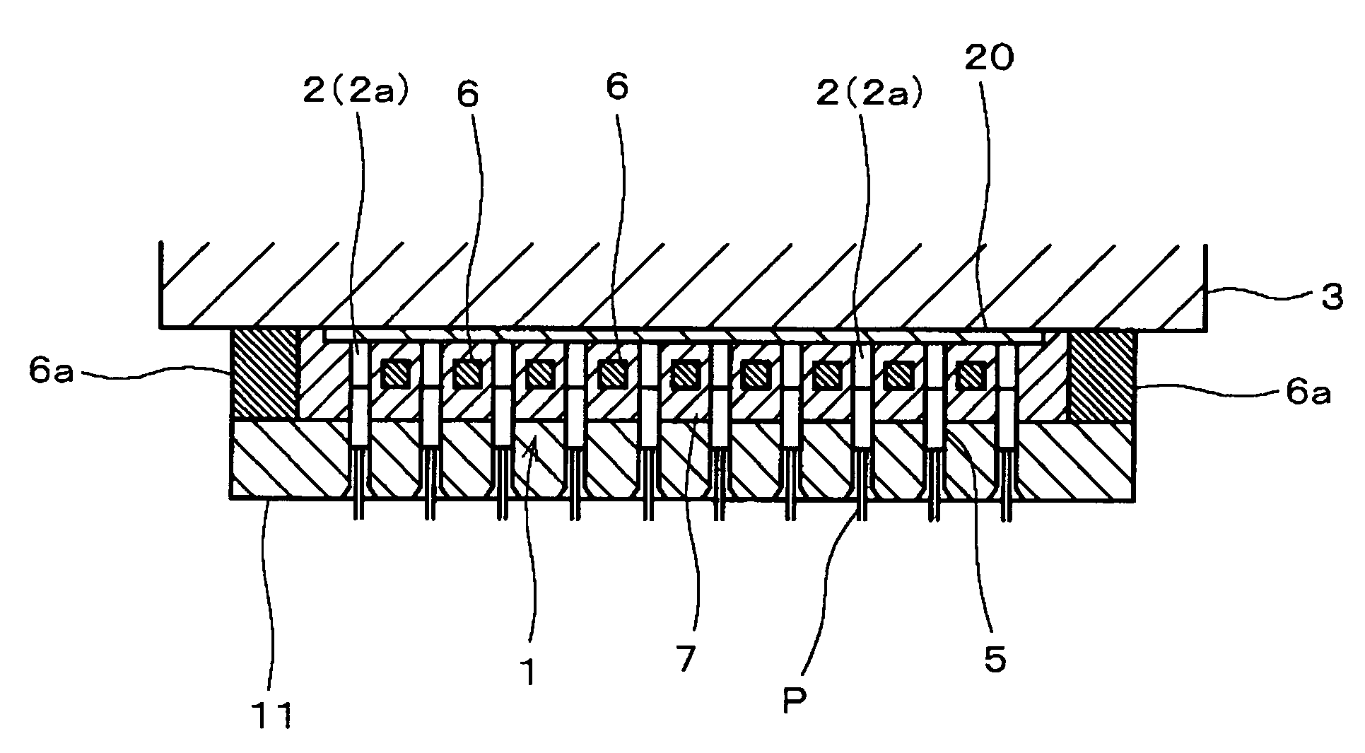
[0017]In order to overcome the problems described above, preferred embodiments of the present invention provide a method and a device for applying a conductive paste to electronic parts in which, when a holding jig holds the electronic parts, the conductive paste is applied to the electronic parts in predetermined thicknesses at predetermined positions with high precision without sacrificing the productivity by decreasing the variance in protrusion distances of the electronic parts from holding holes of a holding jig.

Problems solved by technology

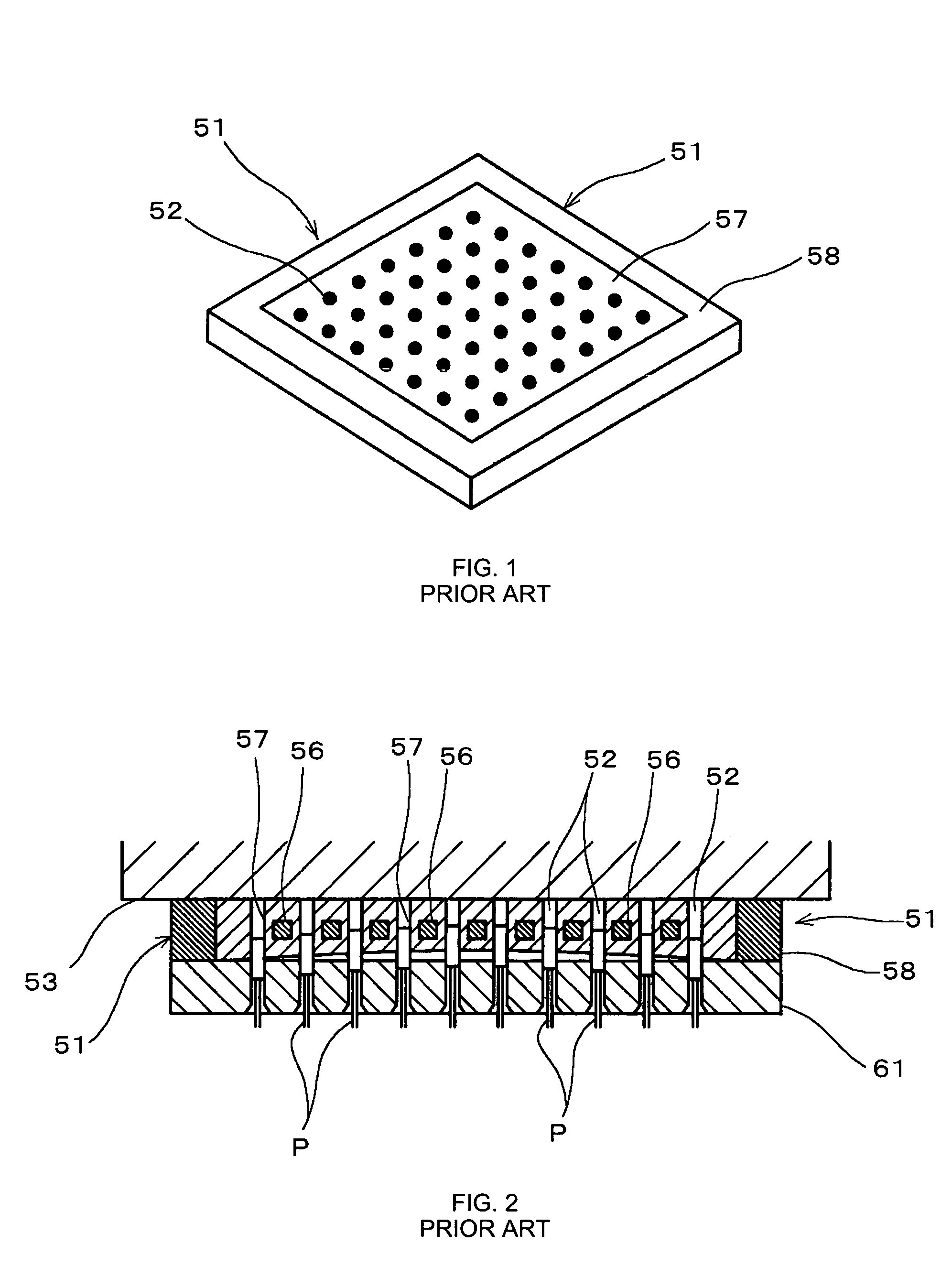
In addition, since the entire holding jig 51 is deformed to be convex upward, the protrusion distances (protrusion heights) of the electronic parts 55 from the holding holes 52 in the center portion disadvantageously become longer.
However, this method increases the time for holding a large number of electronic parts and, thus, the productivity is disadvantageously decreased.
However, since the ends of the electronic parts 55 protruding from the holding holes 52 are urged onto the surface plate 54 with the holding jig 51 parallel to a flat surface of the surface plate 54 as shown in FIG. 6B to align the protrusion distances in this method, an extra step is required and, therefore, the fabrication process is disadvantageously complicated and costly.
Also, since this method still causes the elastic deformation of the elastic material (rubber) 57, the protrusion distances cannot be exactly equal, which is a problem.

Method used


Image

  • Method and device for applying conductive paste
  • Method and device for applying conductive paste
  • Method and device for applying conductive paste

Examples


first embodiment

[0053]In this embodiment, the following case is described as an example: a conductive paste for external electrode formation is applied to electronic parts to form external electrodes on ceramic parts (the electronic parts), each of which having a plurality of internal electrodes laminated and arranged with ceramic layers therebetween in a fabrication process of an electronic component (a laminated ceramic chip capacitor in this example).

[0054]FIG. 7 is a diagram illustrating a method for holding electronic parts in holding holes of a holding jig in a conductive-paste applying process according to the embodiment of the present invention. FIG. 8 is an enlarged view of the relevant portion in FIG. 7. FIG. 9 is a perspective view of the structure of the holding jig.

[0055]As shown in FIGS. 7 to 9, in order to hold electronic parts 5 in this embodiment, the holding jig 1 has a plurality of holding holes 2, and a guide plate 11 has a plurality of through-holes 12 to temporarily hold the e...


PUM

PropertyMeasurementUnit
thicknessaaaaaaaaaa
sizeaaaaaaaaaa
thicknessesaaaaaaaaaa

Abstract

A tabular holding jig has a plurality of holding holes whose side walls are made from an elastic material. When electronic parts are inserted into the holding holes of the holding jig, deflection of the holding jig is prevented by (a) disposing an intermediate plate between the holding jig and a base plate, or (b) using a base plate having a stepped portion with a raised surface that covers an area of the holding jig where the plurality of holding holes is formed.

Description

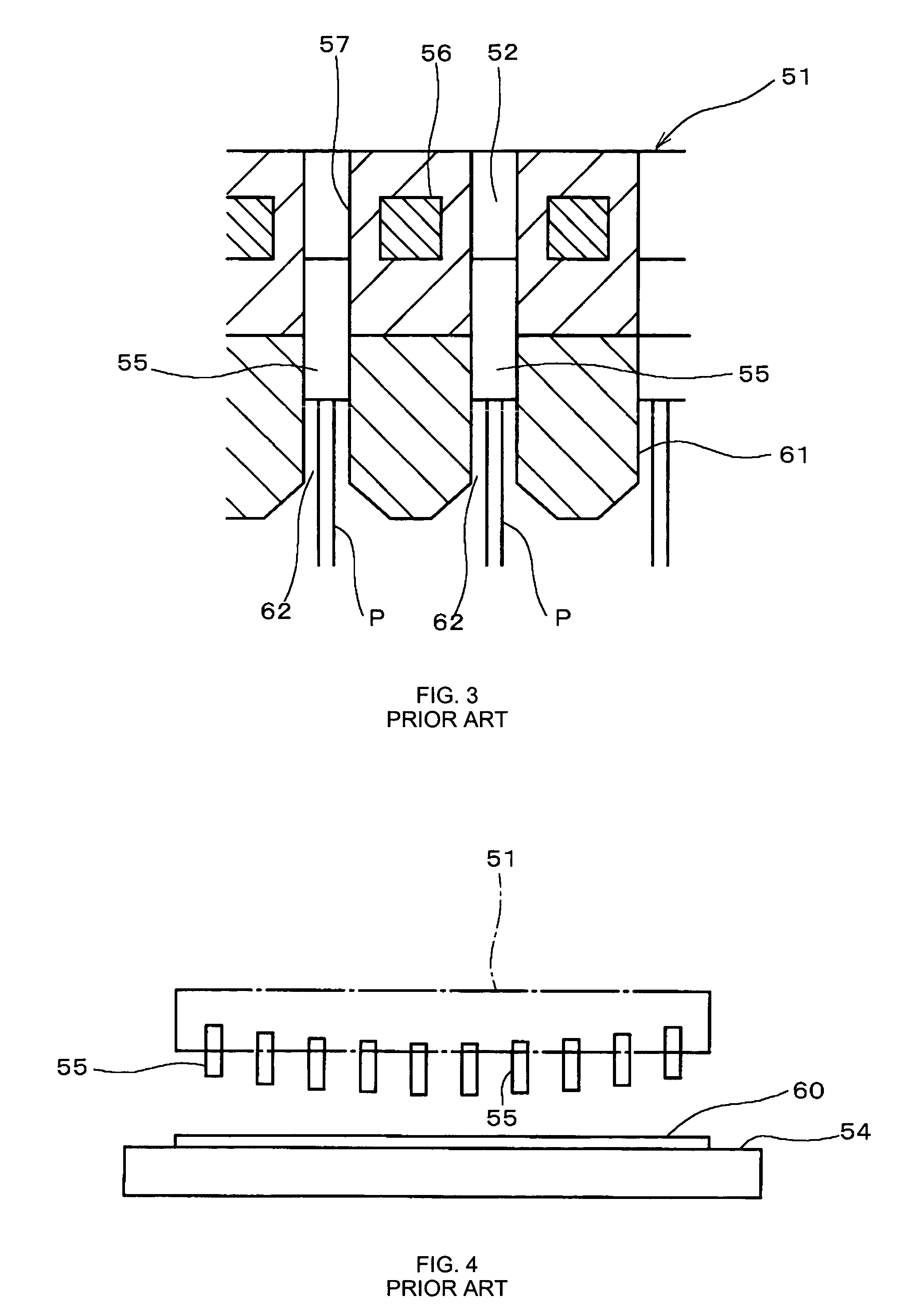
BACKGROUND OF THE INVENTION[0001]1. Field of the Invention[0002]The present invention relates to a method for applying a conductive paste to electronic parts and a device for applying conductive paste used in the method.[0003]2. Description of the Related Art[0004]In a fabrication process of an electronic component, such as a laminated ceramic chip capacitor for example, a method has been widely used in which a conductive paste is applied to the electronic parts and is then cured in order to form external electrodes on electronic parts.[0005]To apply the conductive paste for external electrode formation to the electronic parts, a tabular holding jig 51, shown in FIG. 1, and a guide plate 61, shown in FIGS. 2 and 11, are typically used to cause conductive paste 60 to stick to electronic parts 55, as shown in FIG. 4. As shown in FIG. 1, the holding jig 51 is made from an elastic material (such as rubber) 57, which covers metal core materials 56, shown in FIGS. 2 and 3, and has a plura...

Claims


Application Information

Patent Timeline
Patent Type & Authority Patents(United States)
IPC IPC(8): B05C13/00B05C3/09B05D1/18B05D5/12H01C1/148H01G4/12H01G4/232H01G13/00H01L21/48
CPCH01C1/148H01L21/4853H01G13/006H01G4/232H01G13/00B05C3/09B05D1/18H01G4/12
Inventor SANADA, YUKIOOHKURA, TAKESHINAITO, HIROKAZU
Owner MURATA MFG CO LTD
Learn More