
Retaining system

a technology of retaining system and retaining rod, which is applied in the direction of pedestrian/occupant safety arrangement, vehicular safety arrangement, safety belt, etc., can solve problems such as accidents, and achieve the effects of convenient and convenient transportation, rapid and reliable operation, and sufficient and maximum freedom of movement for passengers

Inactive Publication Date: 2010-04-13
FRIEDRICK MAURER SOHNE GMBH & CO KG
View PDF30 Cites 2 Cited by
  • Summary
  • Abstract
  • Description
  • Claims
  • Application Information

AI Technical Summary

Benefits of technology

"The present invention provides a restraining system for amusement ride passengers that is simple, reliable, and offers optimum safety and freedom of movement for the passengers. The system includes a seat and back rest connected by a seat belt, with a U-like retaining part that surrounds the passenger's pelvic region for securely keeping them in place. The retaining part is designed to be easily adjusted to different passenger sizes and can be locked in place for the safety of the passengers. The system also includes a latching system that allows the passenger to securely hold the seat in different positions. The invention ensures that the passenger is always securely supported in case of emergency situations and allows for optimal alignment with the seat for the passenger's safety. The invention also provides a measuring system to determine the necessary locking position of the retaining device."

Problems solved by technology

These amusement rides such as roller coasters, big dippers, merry-go-rounds and the like mean that the bodies of the passengers are dashed about hither and thither and so subjected to accelerating and retarding forces and also to changes in the direction of motion and unexpected loads, something which on the one hand exhilarates but on the other hand involves the danger of accidents, for example owing to passengers being thrown off the amusement ride.

Method used


Image

  • Retaining system
  • Retaining system
  • Retaining system

Examples


Embodiment Construction

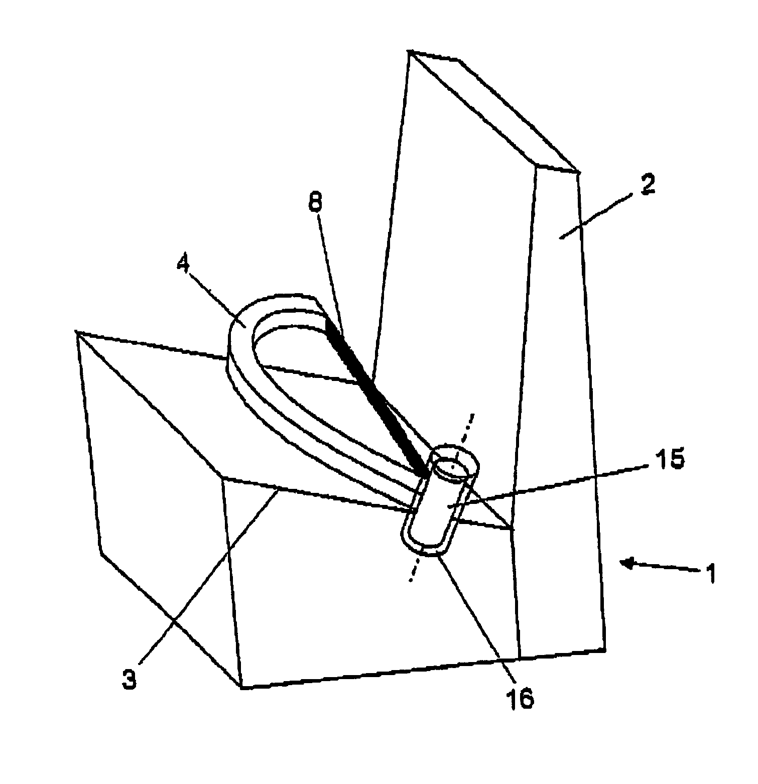
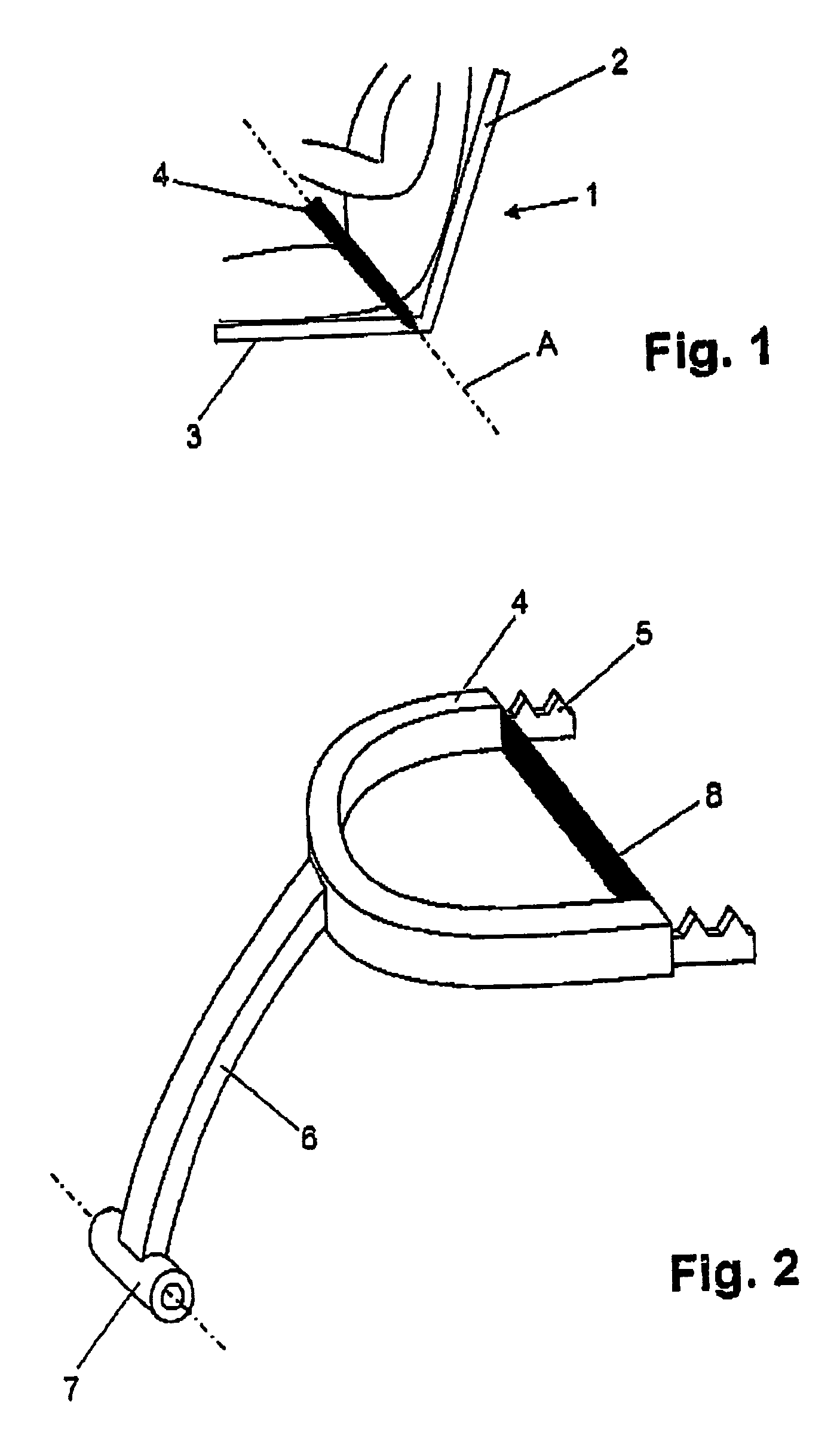
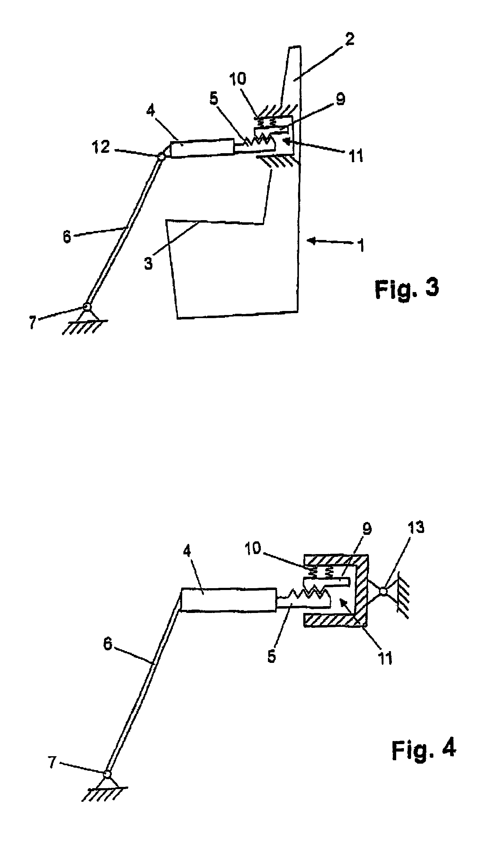
[0035]FIG. 1 shows a lateral view of the principal structure of the retaining system in accordance with the invention. Such structure comprises a chair member 1 with a back rest 2 and a seat 3, a retaining device or a retaining part 4 being provided in the pelvic region of a person or passenger on the chair member whose seat is inclined at an angle of approximately 25° to the horizontal, such retaining part surrounding the passenger or, respectively, his pelvic region like a letter U and being arranged in a plane A making an angle α with the horizontal of preferably approximately 45° and more especially 44.6°. Owing to the arrangement in accordance with the invention in the pelvic region of the passenger to be secured it is possible to ensure that any passenger whether corpulent or slim, tall or short is securely held on the chair member 1 with an optimum freedom of movement and without any danger of falling off in the case of an amusement ride involving somersaulting, steep curves ...


PUM


Abstract

A retaining system for amusement rides, more particularly roller coasters, carrousels or the like has a chair member for a passenger to sit on and which comprises a seat and a back rest and furthermore a retaining device with at least one locking part able to be moved between at least one getting on position and at least one retaining position, the retaining device possessing an essentially U-like retaining part, which at least to a major extent surrounds the pelvic region of the passenger to be secured, the retaining part being inclined in an anthropometrically optimized plane, which is inclined in a range of 30° to 60°, more particularly 40° to 50°, preferably approximately 45° to the horizontal and / or the seat. Furthermore the present invention relates to a measuring system for determination of the optimum locking position, the measuring system comprising a band- or cable-like element 8 arranged at the ends of the U-like retaining part, which element on applying the retaining device to the passenger to be secured engages the passenger to be secured rendering it possible to ascertain the locking or retaining position of the retaining device or, respectively, of the retaining part.

Description

BACKGROUND OF THE INVENTION[0001]This nonprovisional application claims priority under 35 U.S.C. § 119(a) on Patent Application No(s) .102 39 891.7 filed in Germany on Aug. 29, 2002 and 03 018 943.5 filed in Europe on Aug. 20, 2003, which is(are) herein incorporated by reference.[0002]The invention relates to a retaining system, more particularly for persons subjected to dynamic movements such as acceleration, retarding and / or swinging and rotary movements of conveying means, more particularly vehicles and / or working platforms, comprising a chair member for use by such person, said chair member having a seat and a back rest, and furthermore a retaining device having a locking means able to be moved between at least one getting on position and at least one retaining position. The conveying means may be terrestrial, aquatic and / or aerial means of transportation, with which persons may be conveyed while seated. The persons are then subject to dynamic forces and must be secured to preve...

Claims


Application Information

Patent Timeline
Patent Type & Authority Patents(United States)
IPC IPC(8): A62B35/00A63G1/34A47C31/00A47D15/00B60R21/00B60R21/02B60R22/02B60R22/18
CPCB60R21/02B60R22/02B60R22/18B60R2022/1806B60R2021/0213B60R2021/022B60R2022/027B60R2021/0097
Inventor MULLER, ALFREDGETTERT, ROBERT
Owner FRIEDRICK MAURER SOHNE GMBH & CO KG
Learn More