
Control system and method for flash separation

a control system and chromatographic technology, applied in the field of chromatography, can solve the problems that separation conditions that produce acceptable results for one chromatographic method may not, and cannot, produce acceptable results, and achieve the effect of improving separation and increasing the efficiency of the chromatographic system

Active Publication Date: 2010-03-30
BIOTAGE INC
View PDF25 Cites 17 Cited by
  • Summary
  • Abstract
  • Description
  • Claims
  • Application Information

AI Technical Summary

Benefits of technology

[0007]The invention relates to methods and control systems for operating chromatographic apparatus and, in particular the operation of flash separation apparatus using a multi-solvent systems and solvent gradient techniques for achieving improved separation and / or increased efficiency of the chromatographic system.
[0015]The example embodiments of the methods and apparatus for determining conditions for chromatography described here may provide one or more advantages including, for example, options for linear, continuous non-linear and / or stepped gradient profiles for two or more solvents that may be automatically generated from corresponding TLC data and solvent data for simplifying and / or automating the transfer of separation conditions from TLC directly to column chromatography with a high degree of confidence, thereby reducing the need for multiple TLC runs. In connection with generating the gradient profile, the controller may access data for distinguishing between weaker and stronger solvents based on solvent strength values and / or polarity values of the solvents utilized in the solvent system, thus relieving the operator from the need to determine which of the solvents should be the majority solvent at the start of a gradient.

Problems solved by technology

However, the separation conditions that produce acceptable results for one chromatographic method may not, and commonly will not, produce acceptable results if transferred directly to another chromatographic method.
Accordingly, the process of adapting the separation conditions used in one type of chromatography to another type of chromatography has continued to challenge those skilled in the art and typically requires additional experimentation to adapt the initial separation conditions in order to achieve satisfactory results.

Method used


Image

  • Control system and method for flash separation
  • Control system and method for flash separation
  • Control system and method for flash separation

Examples


Embodiment Construction

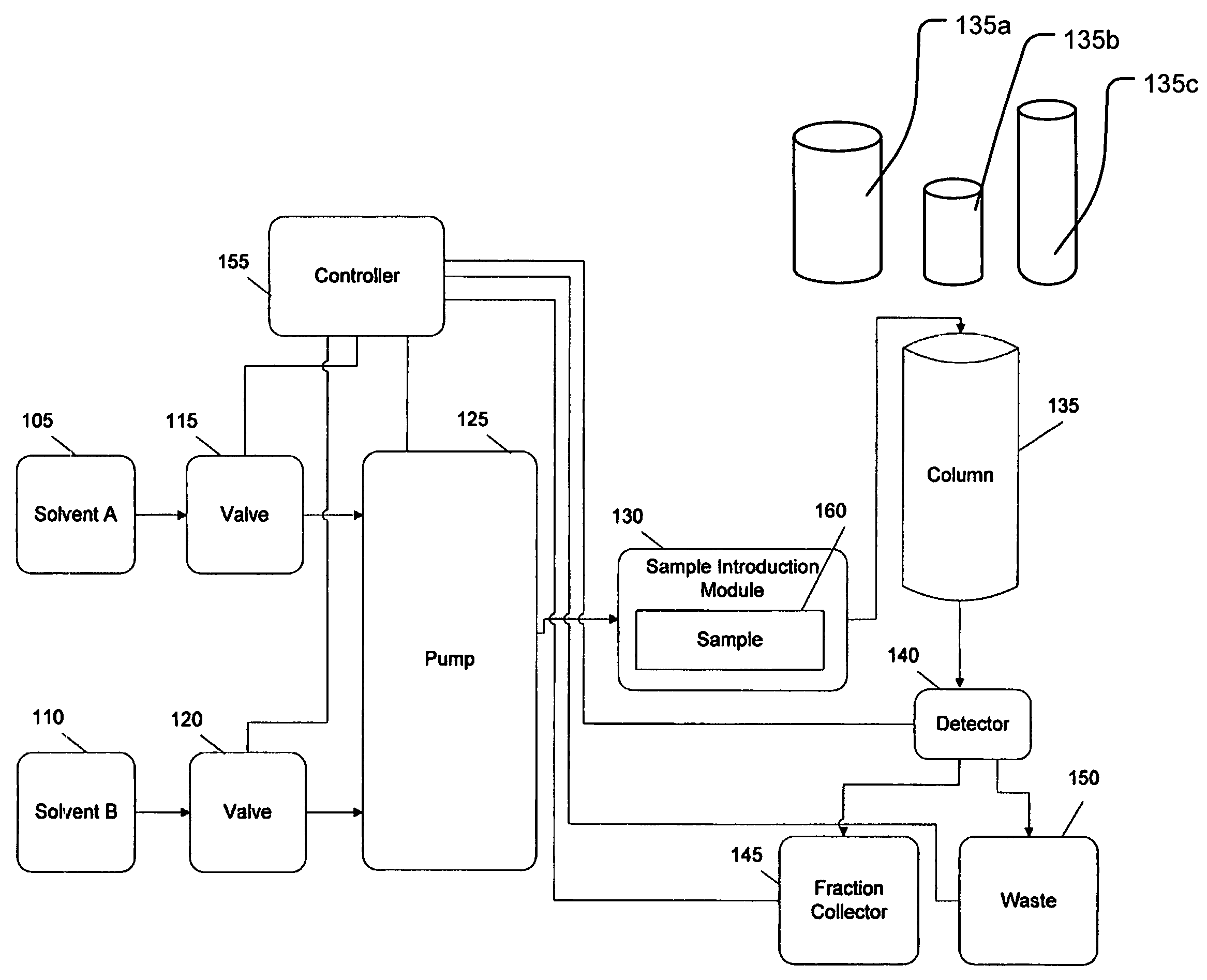
[0030]FIG. 1 is a block diagram of a column chromatography system according to an example embodiment of the invention. As illustrated in FIG. 1, the chromatography system includes solvent sources 105 and 110, valves 115 and 120, a pump 125, a sample introduction module (SIM) 130, a column 135 (which may be selected from a group of available columns 135a, 135b, 135c), a detector 140, a fraction collector vessel 145, a waste collector vessel 150, and a controller 155. Chromatography is performed in the system of FIG. 1 by preparing the chromatography system for use and providing the necessary inputs to the controller 155. Preparing the system for use may include, for example, loading a first solvent A and a second solvent B in the solvent sources 105 and 110, respectively, and loading a sample 160 into the SIM 130.

[0031]Inputs provided to the controller 155 may include, for example, commands corresponding to specific tasks be performed, for example, a command requesting the pump 125 t...


PUM

PropertyMeasurementUnit
distanceaaaaaaaaaa
distanceaaaaaaaaaa
retention factorsaaaaaaaaaa

Abstract

Provided are methods and apparatus for determining conditions for performing chromatography, particularly flash chromatography. The methods may be utilized for separating compounds in a sample in a column chromatography system. The method includes determining at least two retention factors corresponding to the TLC performance of a target compound and an adjacent compound and defining a sample loading amount and a solvent gradient profile using at least two solvents that will result in differential elution of the target and adjacent compounds from a chromatography column. The chromatography system and loading parameters may be selected to provide satisfactory separation of the target compound from adjacent compounds.

Description

PRIORITY STATEMENT[0001]This application is a continuation-in-part of U.S. patent application Ser. No. 10 / 840,450, now abandoned and now published as U.S. Patent Application Publication No. 2005 / 0247625, filed May 5, 2004, and also claims priority under 35 U.S.C. § 119 from U.S. Provisional Patent Application No. 60 / 735,172, which was filed Nov. 10, 2005, the disclosures of which are incorporated herein by reference to the fullest extent consistent with the present disclosure.BACKGROUND OF THE INVENTION[0002]The invention described below relates to chromatography and, more particularly, to chromatography systems and methods of configuring and operating such chromatography systems for improving the separation of various components found within a composition.[0003]Chromatography generally involves the use of one or more solvents to separate a sample composition of multiple components into individual components as a result of the solvents and the sample composition flowing around, over...

Claims


Application Information

Patent Timeline
Patent Type & Authority Patents(United States)
IPC IPC(8): B01D15/08
CPCB01D15/165B01D15/166G01N30/34G01N30/90G01N30/8658G01N30/8679
Inventor HORSMAN, JEFFREY A.BICKLER, JOHN R.
Owner BIOTAGE INC
Learn More