
Inner ring with independent thermal expansion for mounting gas turbine flow path components

a technology of internal ring and gas turbine, which is applied in the direction of machines/engines, forging/pressing/hammering apparatus, etc., can solve the problems of large blade clearance requirement, large gap and corresponding efficiency reduction during some engine operation stages, and the differential thermal expansion of shroud ring segments,

Inactive Publication Date: 2010-03-30
SIEMENS ENERGY INC
View PDF19 Cites 38 Cited by
  • Summary
  • Abstract
  • Description
  • Claims
  • Application Information

AI Technical Summary

Benefits of technology

"The invention is about mounting devices for gas turbine flow path components, specifically shroud ring segments, to minimize the gap between the blade tips and the inner surface of the shroud ring segments under steady-state operating conditions. The invention recognizes that the thermal expansion of the shroud ring segments is different from that of the support structures, such as blade rings, and that this results in a large blade clearance requirement. The invention proposes using a mounting system that allows for independent expansion of the inner and outer rings, reducing the radial expansion rate of the shroud ring and minimizing the power output and efficiency of the engine. The invention also suggests using a low-coefficient thermal expansion material for the inner ring to match the expansion characteristics of the turbine blade tips. The mounting system includes a plurality of radially slidable mounts that allow for radial sliding movement between the inner and outer rings. The invention is designed to minimize differential radial expansion rates between the shroud ring and turbine blades during engine operational transients."

Problems solved by technology

However, the shroud ring segments, blade ring, blades, disks, and their mountings are subject to differential thermal expansion during variations in engine operation, including engine restarts.
This requires a larger gap and a corresponding efficiency reduction during some stages of engine operation.
This creates a large blade clearance requirement, partly because of the time delay between heating of flow path components and their more-insulated support structures.

Method used


Image

  • Inner ring with independent thermal expansion for mounting gas turbine flow path components
  • Inner ring with independent thermal expansion for mounting gas turbine flow path components
  • Inner ring with independent thermal expansion for mounting gas turbine flow path components

Examples


Embodiment Construction

[0015]The present inventors have recognized that isolating the thermal expansion of a shroud ring from that of its support structure could minimize differential radial expansion rates between the shroud ring and turbine blades during engine operational transients. This would allow minimizing the radial expansion rate of the shroud ring, thus allowing less clearance between the blades and the shroud ring, increasing power output and efficiency.

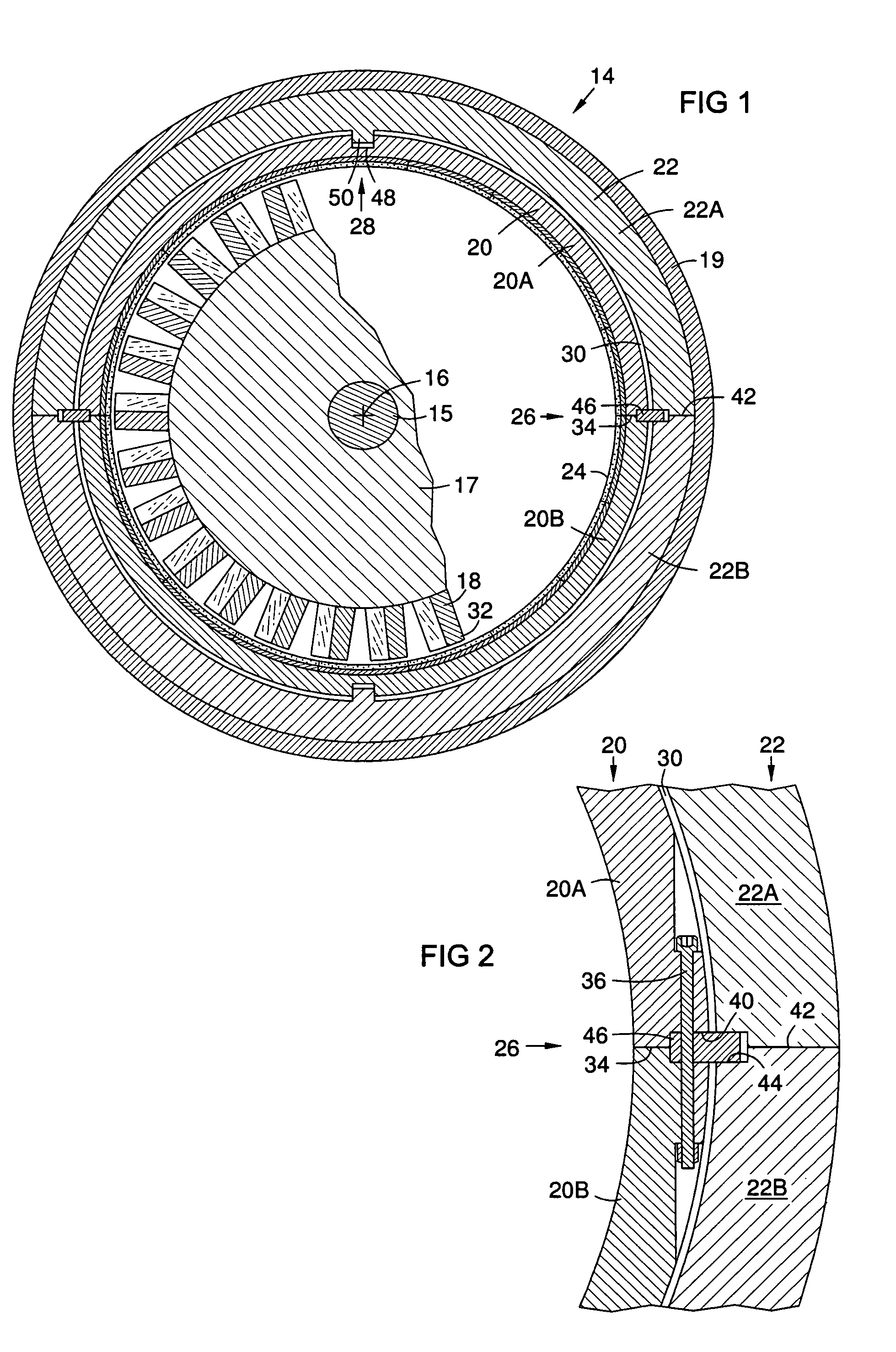
[0016]FIG. 1 is a conceptual view of a cross section of a gas turbine 14 with a turbine shaft 15, a shaft axis 16, a disk 17, and blades 18 in a case 19. An inner ring 20 according to the invention is mounted within an outer ring 22. Shroud ring segments 24 are mounted on the inner ring 20. The outer ring 22 may be made of a first material with a first coefficient of linear thermal expansion, and the inner ring 20 may be made of a second material with a lower coefficient of thermal expansion than that of the first material. The inner ring 20 is...


PUM

PropertyMeasurementUnit
temperaturesaaaaaaaaaa
coefficient of thermal expansionaaaaaaaaaa
circumferenceaaaaaaaaaa

Abstract

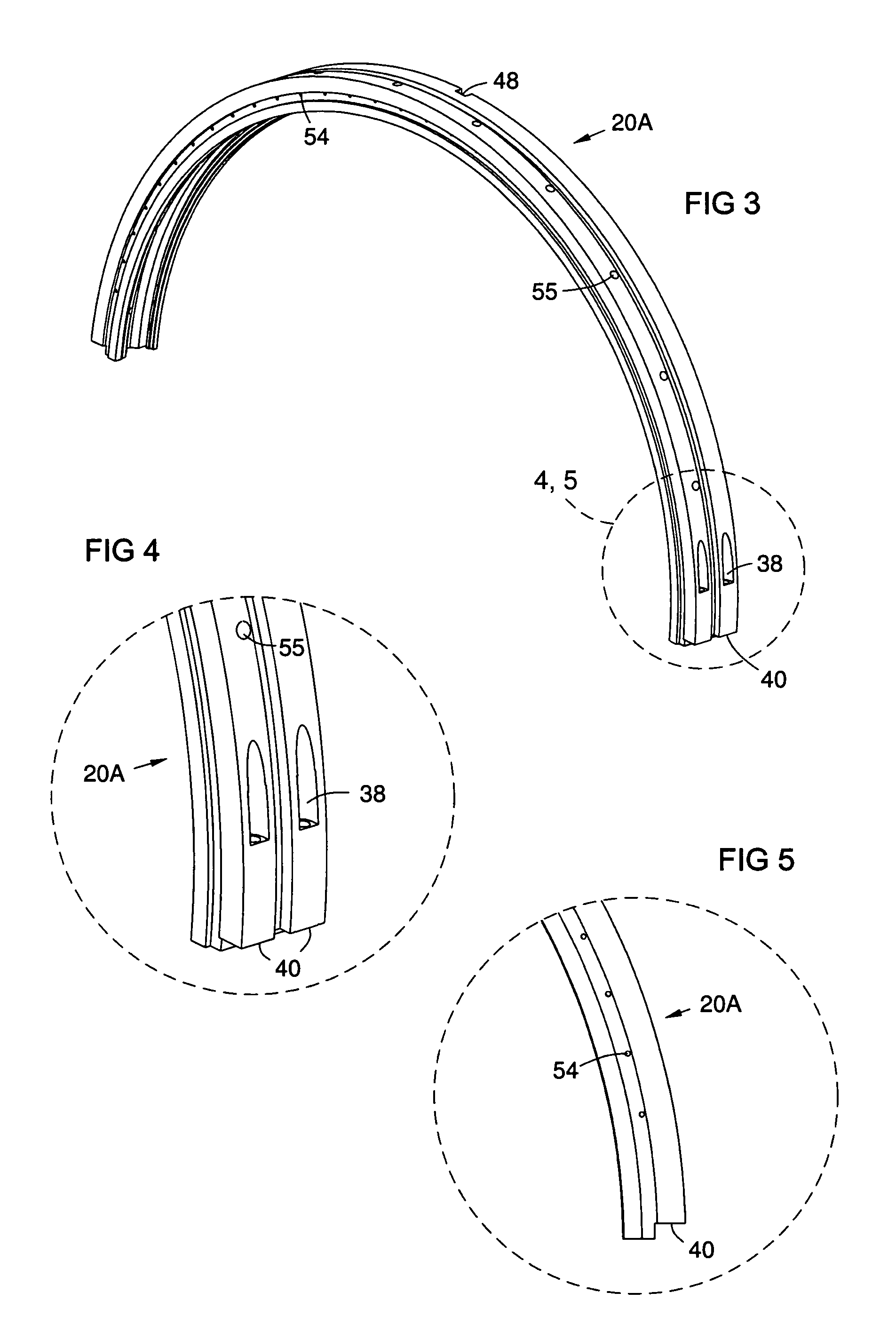
An inner mounting ring (20) for gas turbine flow path components such as shroud ring segments (24). The inner ring (20) may be mounted to an outer ring (22) on radially slidable mounts (26, 28) that maintain the two rings (20, 22) in coaxial relationship, but allows them to thermally expand at different rates. This allows matching of the radial expansion rate of the inner ring (20) to that of the turbine blade tips (32), thus providing reduced clearance (33) between the turbine blade tips (32) and the inner surface of the shroud ring segments (24) under all engine operating conditions. The inner ring (20) may be made of a material with a lower coefficient of thermal expansion than that of the outer ring (22).

Description

FIELD OF THE INVENTION[0001]The invention relates to mounting devices for gas turbine flow path components, and particularly those for mounting shroud ring segments to minimize clearance between the turbine blade tips and the inner surface of the shroud ring segments under steady-state operating conditions.BACKGROUND OF THE INVENTION[0002]A gas turbine shaft supports a series of disks. Each disk circumference supports a circular array of radially oriented aerodynamic blades. Closely surrounding these blades is a refractory shroud that encloses the flow of hot combustion gasses passing through the engine at temperatures of over 1400° C. The shroud is assembled from a series of adjacent rings supporting flow path components that are typically made of one or more refractory materials such as ceramics. Shroud rings that surround turbine blades are normally formed of a series of arcuate segments. Each segment is attached to a surrounding framework such as a metal ring called a blade ring...

Claims


Application Information

Patent Timeline
Patent Type & Authority Patents(United States)
IPC IPC(8): F01D25/26
CPCF01D11/18F01D25/246F05D2230/60Y10T29/4932F05D2300/50212Y10T29/49323F05D2230/642
Inventor CHEHAB, ABDULLATIF M.WAECHTER, SCOTT T.LIGHT, KEVIN M.TERPOS, BRIAN H.PU, ZHENGXIANG
Owner SIEMENS ENERGY INC
Learn More