
Vehicle vision system with high dynamic range

Active Publication Date: 2010-03-23
GENTEX CORP +1
View PDF73 Cites 119 Cited by
  • Summary
  • Abstract
  • Description
  • Claims
  • Application Information

AI Technical Summary

Benefits of technology

[0016]In at least one embodiment, a control system configured to activate a light source and, or, to acquire images from an image sensor is provided. In at least one related embodiment, the control system is configured to acquire at least one first image while a light source is at least partially energized and is configured to acquire at least one second image while the light source is de-energized and is configured to generate a synthetic image by subtracting the second image from the first image on a pixel by pixel basis. In at least one related embodiment, a light source is configured to be at least partially energized and at least partially de-energized in succession to produce a coded pattern and the control system is configured to acquire

Problems solved by technology

High intrascene dynamic range, the range of brightness of objects which can be detected within a single frame, is more technically challenging to achieve.
As a result, such sensors are typically more expensive.
The most significant problem with known vehicular vision systems is the washout and blooming that occurs from oncoming vehicle headlamps or other lamps within the scene.
For conventional image sensors, this results from the fact that the image sensor pixels do not possess the dynamic range to sense both bright headlamps and the faint objects in the scene.
If the sensitivity of the imager is set sufficiently high for adequate imaging of the scene when illuminated by a NIR light source, oncoming headlamps will substantially saturate the area of the imaged oncoming vehicle and severely limit the ability to see faint objects close in proximity to the oncoming vehicle.
If the imager's sensitivity is set such that oncoming headlamps do not saturate the image, faint objects in the scene are not visible, thus negating most benefits of the night vision system.
Electronic blooming occurs in some image sensors when electrons generated in one pixel spill over into neighboring pixels, resulting in bright objects being imaged as a much larger object than they actually are and thus inhibiting the ability to resolve other objects in close proximity to the bright object.

Method used


Image

  • Vehicle vision system with high dynamic range
  • Vehicle vision system with high dynamic range
  • Vehicle vision system with high dynamic range

Examples


Embodiment Construction

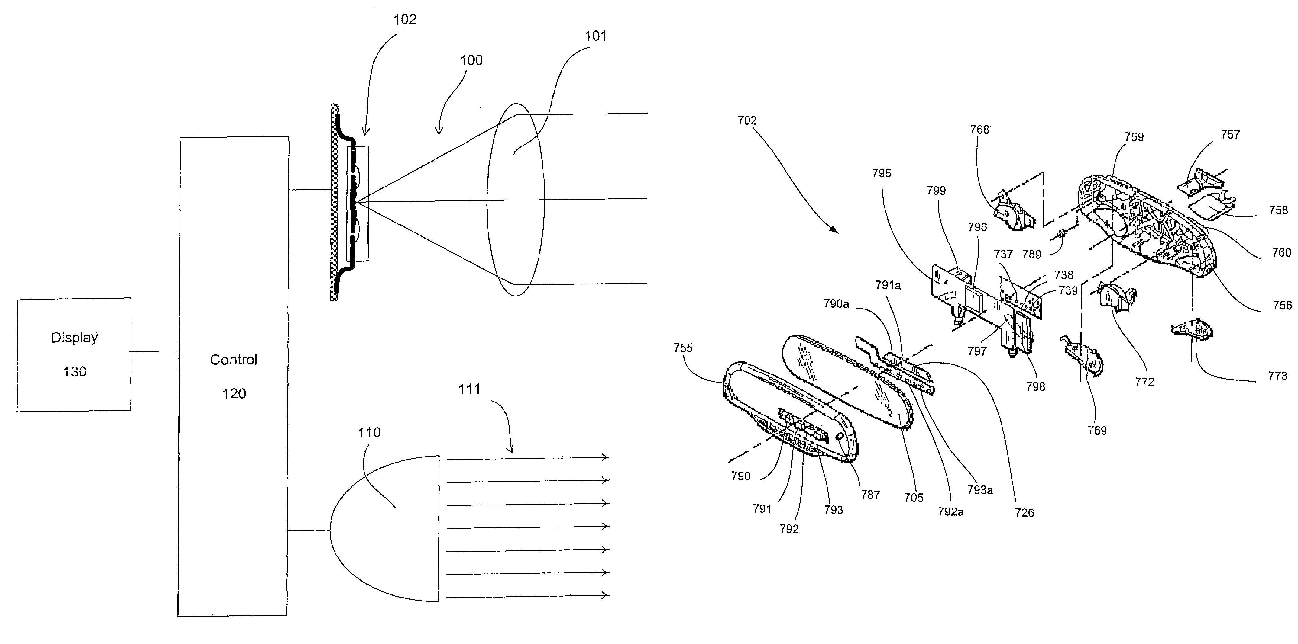
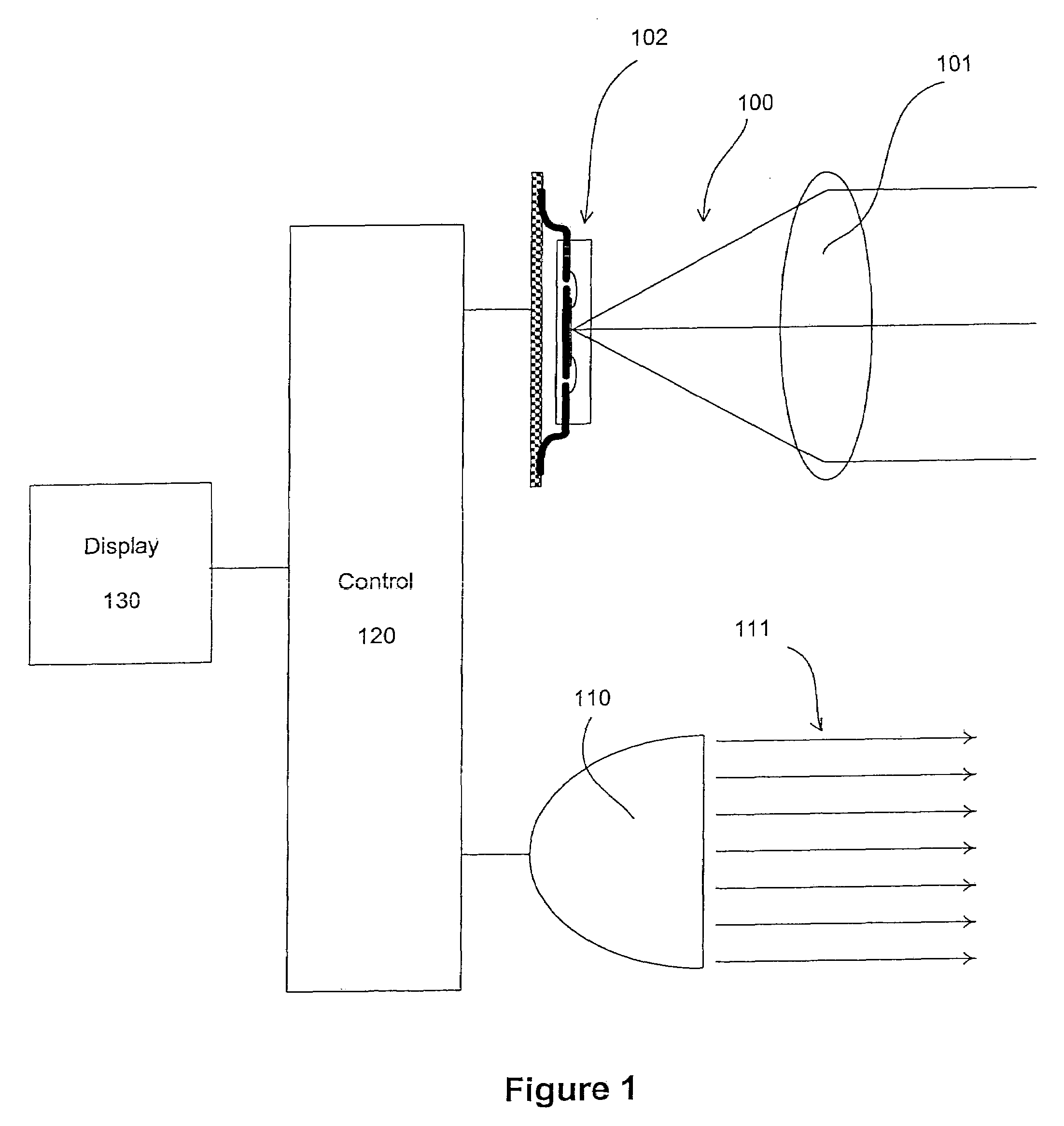
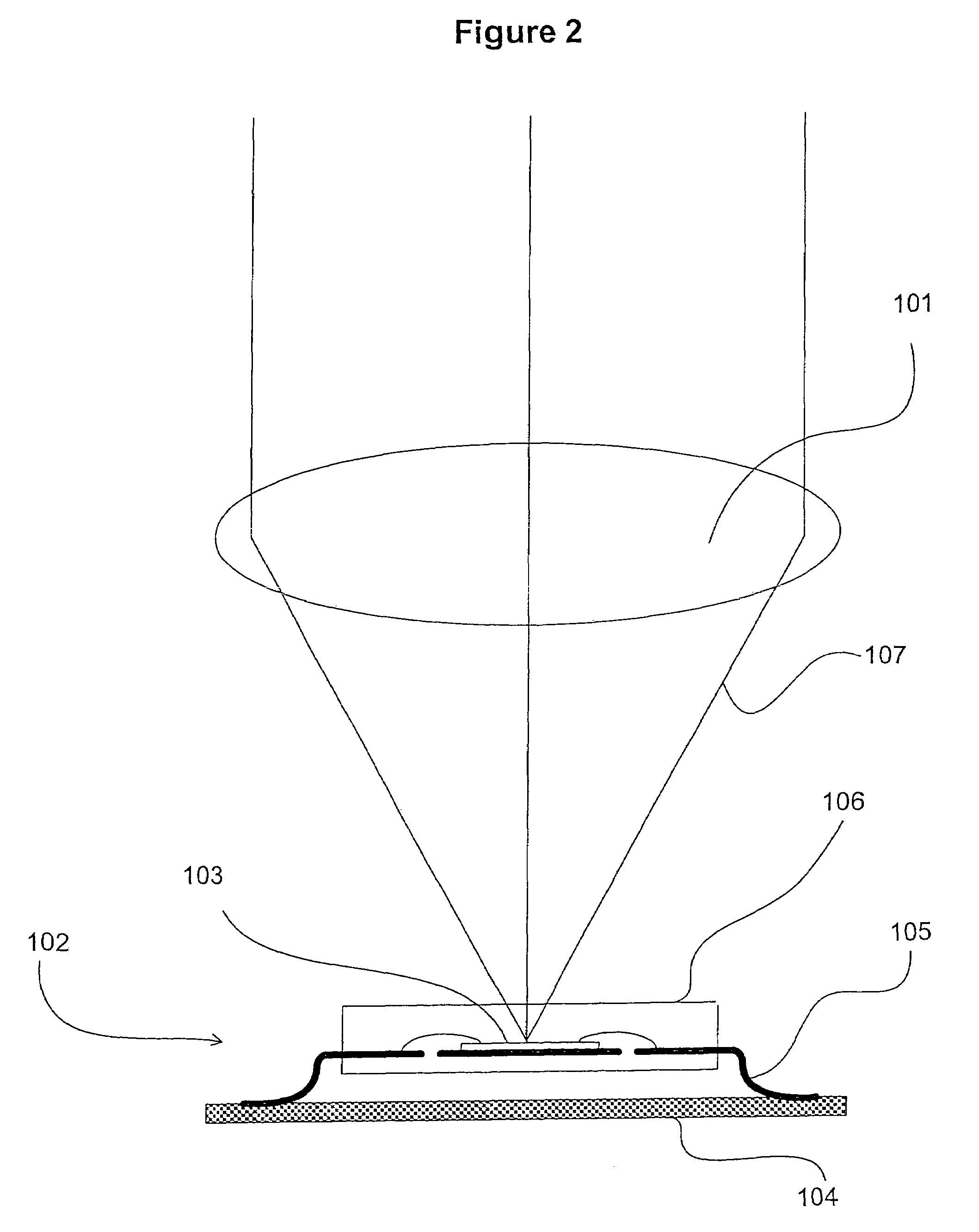
[0026]A vehicular vision system with high dynamic range for use as a night vision system and, or, for other vehicular applications may be constructed utilizing a high dynamic range image sensor as depicted in FIG. 1. An imaging assembly 100 comprises an image sensor assembly 102 and a lens system 101. The lens system 101 forms an image of the forward scene of the controlled vehicle that is sensed electronically by the image sensor assembly 102. A NIR light source 110 projects NIR illumination, shown as NIR light rays 111, onto the scene to be imaged. The use of NIR illumination for the forward scene is advantageous because it can be sensed by electronic imaging technology but is not visible to humans and thus will not cause glare to other drivers. Therefore, the scene can be illuminated such that faint objects even at long distances may be detectable by image sensor assembly 100.

[0027]NIR light source 110 may be of various types such as an incandescent light source or high-intensity...


PUM

PropertyMeasurementUnit
Fractionaaaaaaaaaa
Nanoscale particle sizeaaaaaaaaaa

Abstract

A vehicular vision system is disclosed comprising a high dynamic range. The systems and methods are advantages for rear vision, collision avoidance, obstacle detection, adaptive cruise control, rain sensing, exterior light control, and lane departure warning, as well as other applications where a given scene may comprise objects having widely varying brightness values.

Description

CROSS-REFERENCE TO RELATED APPLICATION[0001]This application claims priority under 35 U.S.C. §119(e) to the following: U.S. Patent Provisional Application No. 60 / 394,583, entitled “VEHICLE VISION SYSTEM WITH HIGH DYNAMIC RANGE,” filed on Jul. 9, 2002, Joseph S. Stam et al. The disclosure of the above-referenced provisional application is incorporated herein in its entirety.BACKGROUND OF THE INVENTION[0002]Several vehicle vision applications that utilize an image sensor to either control a vehicle function or provide an image to a driver have been proposed. Example applications include exterior light control, rain sensing, obstacle detection, collision avoidance, adaptive cruise control, lane departure warning, and night vision systems. Many image sensor technologies can provide for a wide interscene dynamic range by adjusting exposure between frames. High intrascene dynamic range, the range of brightness of objects which can be detected within a single frame, is more technically cha...

Claims


Application Information

Patent Timeline
IPC IPC(8): G01J5/02B60R21/00B60R1/062B60R1/12G08G1/16H01L27/14H04N5/225H04N5/235H04N5/335
CPCB60R1/062B60R1/12G02B23/12H01L27/14621G02B1/11B60R2001/1223H01L27/14654H01L27/14625
Inventor STAM, JOSEPH S.BERENDS, KEITH H.BUSH, GREGORY S.BANKS, JEREMY B.WALSTRA, ERIC J.
Owner GENTEX CORP
Learn More