
Magnetic bearing system

a bearing system and magnetic technology, applied in the direction of magnetic bodies, machines/engines, liquid fuel engines, etc., can solve the problems of poor feedback characteristics in the high frequency range, increased processing load, and increased cost, so as to reduce processing load, enhance high-frequency characteristics, and simplify demodulation operation

Active Publication Date: 2010-03-16
SHIMADZU CORP
View PDF10 Cites 10 Cited by
  • Summary
  • Abstract
  • Description
  • Claims
  • Application Information

AI Technical Summary

Benefits of technology

The present invention provides a magnetic bearing system that simplifies demodulation operations and achieves enhanced high-frequency characteristics while reducing processing load associated with bearing control. The system includes carrier generation means, detection means, and A / D conversion means. The carrier generation means generates a carrier signal by digital processing, and the detection means modulates the carrier signal based on the support position of the object. The A / D conversion means converts the modulated signal to a digital signal at a sampling frequency that satisfies a certain relation. The system can control multiple objects and has a simplified demodulation operation. The technical effects of the invention include improved high-frequency characteristics, reduced processing load, and improved demodulation operation.

Problems solved by technology

Thus, depending on a processing speed of digital signal processor (DSP), the maximum frequency fr cannot be set at a desirably high value, resulting in poor feedback characteristics in a high frequency range.
Specifically, while it is conceivable to increase the sampling frequency fs and / or the carrier frequency as measures for avoiding the problem about deterioration in the high-frequency characteristics, these measures will inevitably impose higher processing load on a DSP, and lead to the need for a DSP operating at high frequencies, causing an increase in cost.
Moreover, if the digital demodulation is performed in a conventional manner, an S / N ratio will deteriorate due to signal decay occurring during the demodulation operation, which is likely to cause vibration in the rotor which is an object to be supported.

Method used


Image

  • Magnetic bearing system
  • Magnetic bearing system
  • Magnetic bearing system

Examples


Embodiment Construction

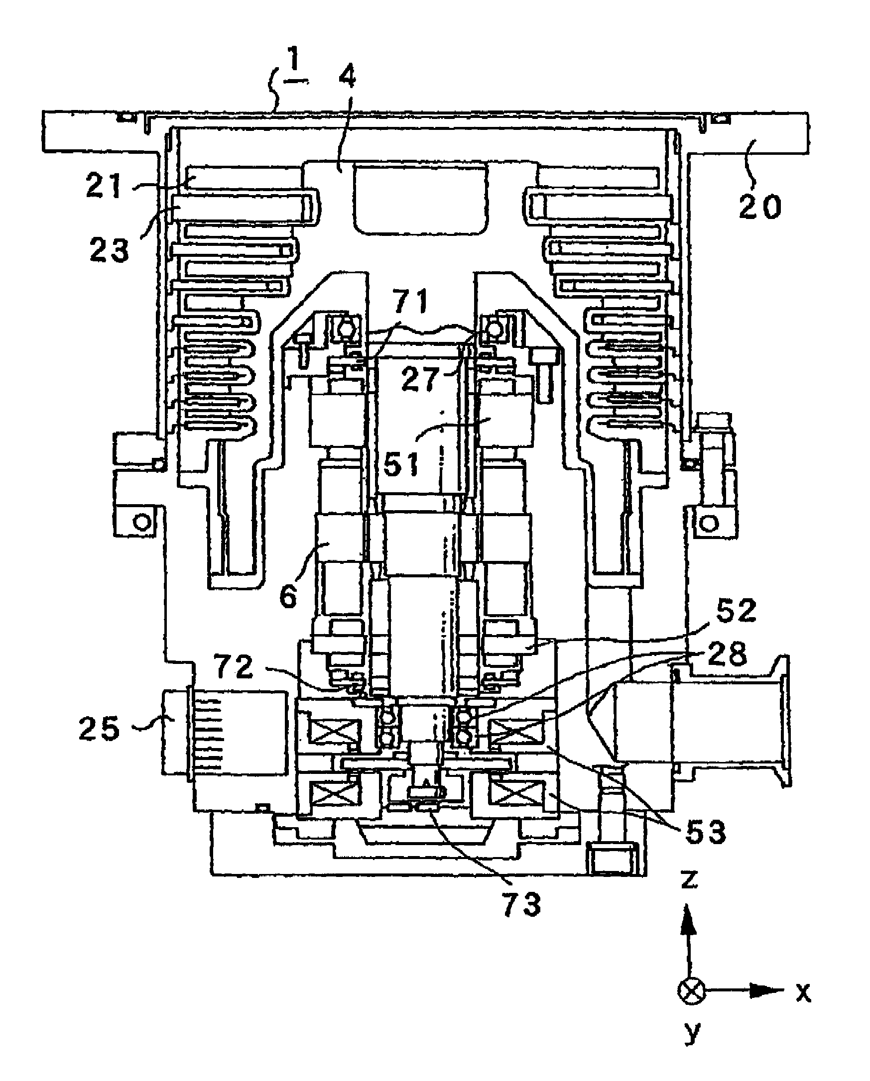
[0029]With reference to the drawings, an exemplary embodiment of the present invention will now be described. FIG. 1 is a sectional view showing a schematic structure of a pump body 1 of magnetic bearing-type turbo-molecular pump. The following description will be made based on an example where the present invention is applied to a 5-axis control-type magnetic bearing system provided in the turbo-molecular pump. As shown in FIG. 1, the 5-axis control-type magnetic bearing system of the turbo-molecular pump is designed such that a rotor 4 formed with plural stages of rotor blades 21 is supported by two electromagnets 51, 52 constituting a radial magnetic bearing, and an electromagnet 53 constituting an axial magnetic bearing, in a non-contact manner.

[0030]The turbo-molecular pump has a plurality of stator blades 23 which are fixed to an inner wall of a casing 20 in a multistage manner along an axial direction (vertical direction in FIG. 1) in such a manner as to be arranged alternate...


PUM


Abstract

Disclosed is a magnetic bearing system capable of simplifying a demodulation operation and reducing a processing load associated with a magnetic levitation control. A carrier signal having a frequency fc is apply to a sensor through a filter. The sensor operates to modulate the carrier signal, and a difference amplifier operates to calculate a difference between the amplitude-modulated signal FAM (t) and a sensor reference signal Fstd (t). An A / D converter operates to A / D convert a difference signal Fsub (t) output from the difference amplifier to a discretized sensor signal. In the A / D conversion, a sampling frequency fs is set to satisfy the following relation: fc: fc=n·fs or fc=fs / 2 (n is a natural number). Thus, the discretized sensor signal includes no carrier wave, and therefore a demodulation operation which has been previously essential can be simplified.

Description

BACKGROUND OF THE INVENTION[0001]1. Field of the Invention[0002]The present invention relates to a magnetic bearing system for use in a turbo-molecular pump, a machine tool or the like.[0003]2. Description of the Related Art[0004]A magnetic bearing system is often used in equipment requiring high-speed rotation, such as a turbo-molecular pump or a machine tool. The magnetic bearing system is designed to detect a displacement of a rotor using a displacement sensor, and feed back the detection result to control an excitation current of an electromagnet. Specifically, the displacement sensor is typically composed of an inductance type which is operable to amplitude-modulate a carrier applied thereto, depending on an impedance change resulting from a change in a gap relative to the rotor. After A / D converting the amplitude-modulated signal, the digital signal is demodulated, and the demodulated displacement signal is used for controlling the excitation current of the electromagnet (see,...

Claims


Application Information

Patent Timeline
Patent Type & Authority Patents(United States)
IPC IPC(8): F16C32/04H01H47/00H02K7/09
CPCF04D19/042F04D29/048F04D29/058F16C32/0451F16C2360/45
Inventor KOZAKI, JUNICHIROOHFUJI, MASAKI
Owner SHIMADZU CORP
Learn More