
Deformable variable-stiffness cellular structures

a cellular structure and variable technology, applied in the field of smart materials and intelligent structures, can solve the problems of low stiffness and strength, affecting the bending stiffness of the cellular structure, and affecting the shape and form of the structural component, so as to improve the bending stiffness over the cellular structure, the effect of facilitating strain and shape recovery

Active Publication Date: 2010-03-16
HRL LAB
View PDF10 Cites 79 Cited by
  • Summary
  • Abstract
  • Description
  • Claims
  • Application Information

AI Technical Summary

Benefits of technology

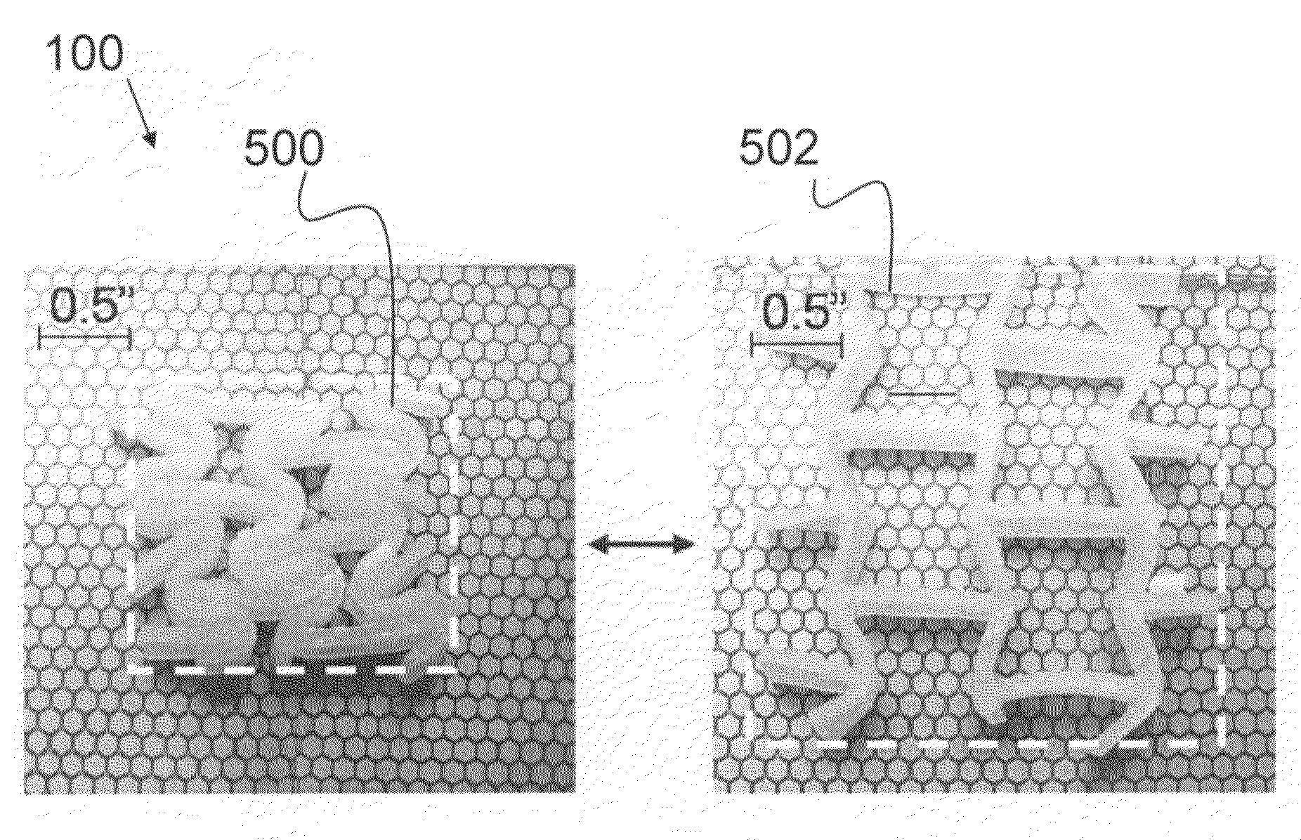
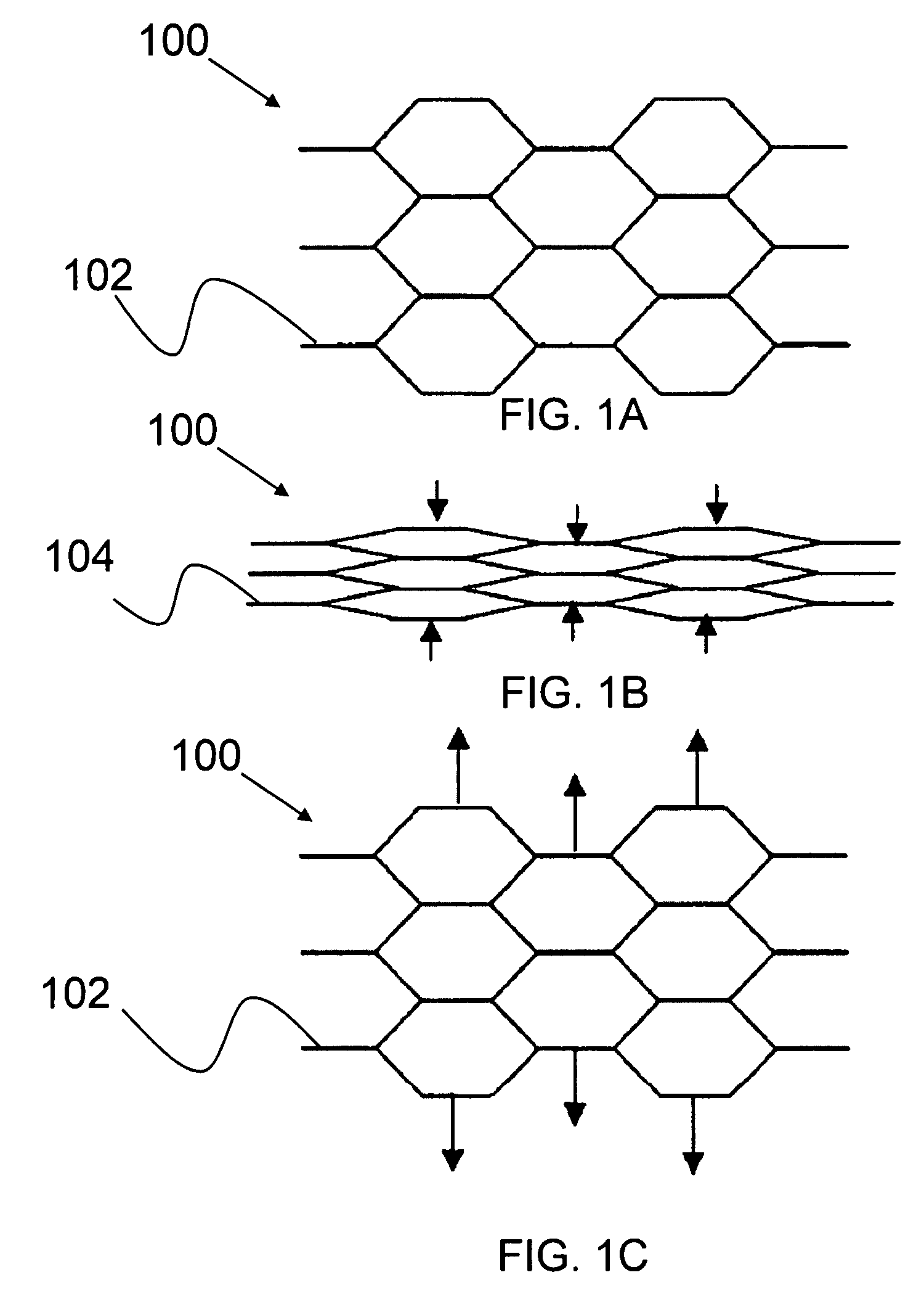
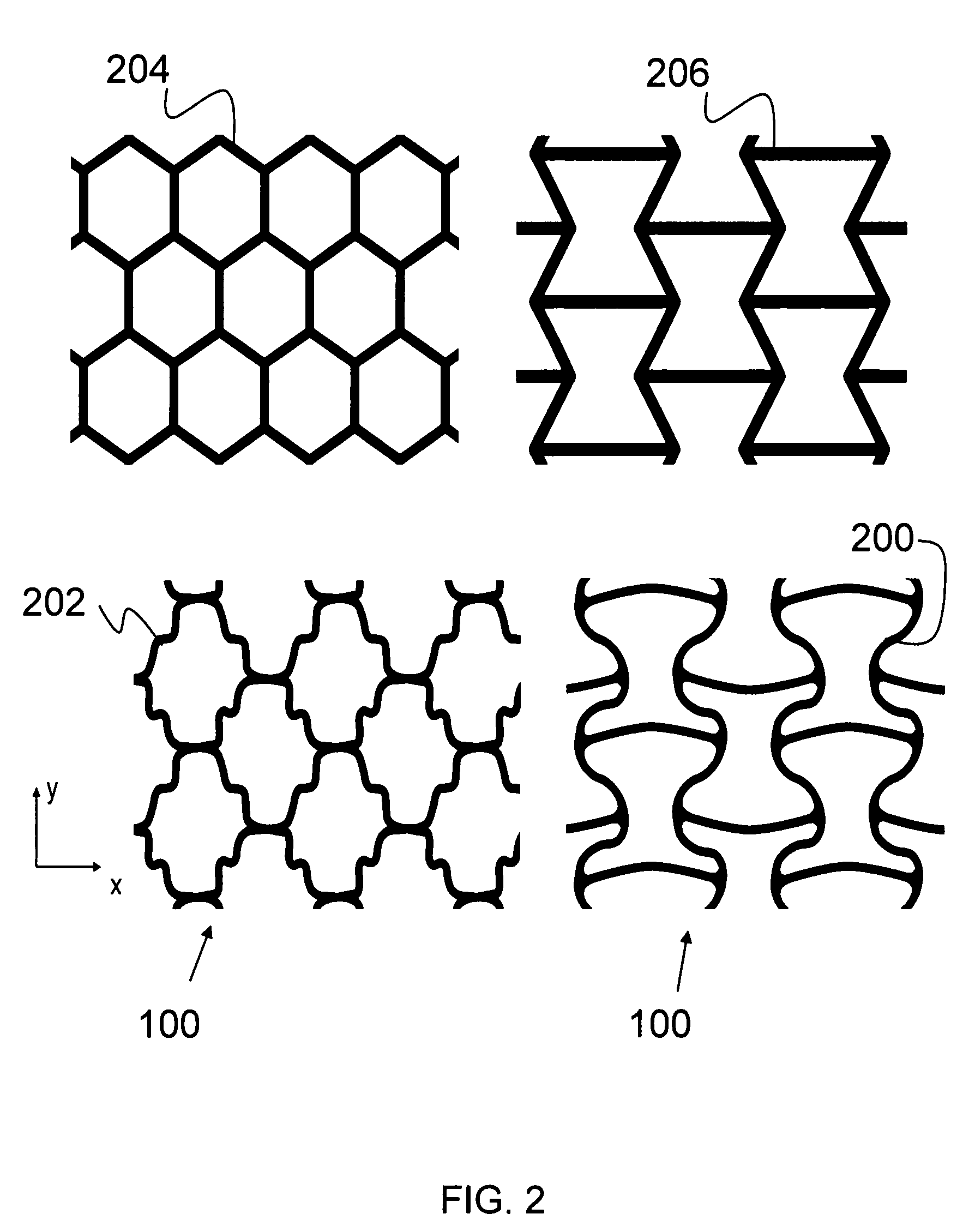
The present invention relates to a deformable cellular structure that can change its shape by applying a stiffness-changing field. The structure is made of a variable-stiffness composite material (VSM) that has a first stiffness state and a second stiffness state. The structure can be locked in the second shape by removing the stiffness-changing field. The cellular structure can be deformed using an actuator that applies a force or displacement to the edges or at various locations within the cellular structure. The structure has a negative Poisson ratio and can accommodate global tensile stretching through cell wall bending. The cellular structure can be created using a solid outer skin covering the external surface or a vacuum-based system. The cellular structure has a gradation of stiffness properties to control the local and global strain of the whole structure. The cellular structure can be deformed by softening the VSM, actuating an actuator, or releasing the actuator signal. The cellular structure can be locked in the first shape and then returned to the second shape by reversing the stiffness-changing field. The cellular structure has a cellular geometry selected from a group consisting of plane symmetry groups. The actuation signal can be selected from a group consisting of a temperature change, redox reaction, pH change, electromagnetic field, chemical reaction, electric current, or an active material in at least one cell.

Problems solved by technology

However, a significant change in shape and form of the structural component is hampered by the sub-optimal use of linear elastic materials.
Conventional design methodologies using linear elastic materials are an inappropriate choice for large structural shape changes.
In one case, the structural components can be designed such that stiffness and strength are low, but the overall reversible deformation is large.
In another approach the structure may be designed such that the system exhibits high stiffness, but as a result the reversible deformation capability of the structure is limited.
In addition, high stiffness materials cannot be made to produce significant “Gaussian Curvature” or simultaneous curvature about two orthogonal axes because this requires a change in area in the plane of the deformation.
The Poisson effect severely limits the ability of linear elastic materials to change area.
While this property is currently available using polymers, especially shape memory polymers, these materials used in their bulk form are difficult to control, and building up thick sections for adequate bending stiffness results in slow responding structures.
Current structure design using static component shapes often requires a compromise between various operational conditions rather than optimization over a range of conditions.
If an intermittent change in structure is required, for example in the stowing or deploying of a structure, reconfiguring of an aircraft wing from a take-off or landing configuration to a cruising configuration, current solutions require extra components and added complexity is incurred.
This concept is limited in the total change in stiffness achievable, and it is not nearly as robust as a material that exhibits intrinsic change in stiffness.
In addition, this approach is not applicable to creating stiffness changes or structural shape changes in large planar surface components.
The limitation of these materials comes from the use of fibers as the reinforcement agent, which undergo micro buckling in order to achieve high compressive strain.
In addition the process of microbuckling can be difficult to control in terms of the direction of microbuckling (i.e. in-plane or out of plane).
Another important limitation of these materials in the case of deforming surfaces is a limitation in the amount of area change (simultaneous strain in two orthogonal directions) that can be achieved due to the inextensibility and length of the reinforcing fibers.
While this approach is advantageous in some applications, it is generally limited in the number of configuration states that can be achieved and optimized.
Therefore, it is not as effective when more than one pre-specified range of motion is desired.

Method used


Image

  • Deformable variable-stiffness cellular structures
  • Deformable variable-stiffness cellular structures
  • Deformable variable-stiffness cellular structures

Examples


Embodiment Construction

[0055]The present invention relates to a morphing cellular structure that includes a variable-stiffness material (VSM) that responds to external stimuli to change its stiffness state. More specifically, the present invention relates to deformable variable-stiffness cellular structure that can be deformed to a desired shape after varying the stiffness of the VSM, with the cellular structure thereafter being lockable in the desired shape by increasing the stiffness of the VSM.

[0056]The following description, taken in conjunction with the referenced drawings and / or tables, is presented to enable one of ordinary skill in the art to make and use the invention. Various modifications will be readily apparent to those skilled in the art, and the general principles defined herein may be applied to a wide range of aspects. Thus, the present invention is not intended to be limited to the aspects presented, but is to be accorded the widest scope consistent with the principles and novel features...


PUM

PropertyMeasurementUnit
stiffnessaaaaaaaaaa
stiffness propertyaaaaaaaaaa
areaaaaaaaaaaa

Abstract

Described is a deformable, variable-stiffness cellular structure. The cellular structure a group of unit cells with each unit cell having a cellular geometry. The group of unit cells are formed of a variable-stiffness composite material (VSM). The VSM has a first stiffness state and a second stiffness state. Additionally, the cellular structure has a first shape and a second shape, with a gradation of shapes between the first shape and second shape. The transition from the first shape to the second shape occurs through using an actuation signal to actuate the VSM to change the stiffness of the cellular structure, thereby allowing the cellular structure to be deformed from the first shape to the second shape, and any shape therebetween. The cellular structure can be locked in the second shape through actuating the VSM from the second stiffness state to the first stiffness state.

Description

PRIORITY CLAIM[0001]The present application claims the benefit of U.S. Provisional Application No. 60 / 778,245, filed Mar. 1, 2006, the present application is also a continuation-in-part of prior application Ser. No. 11 / 051,758, filed Feb. 3, 2005 and prior application Ser. No. 11 / 193,148, filed Jul. 29, 2005.STATEMENT OF GOVERNMENT INTEREST[0002]This invention was made with U.S. Government support under Contract No. FA8650-05-C-7215. The U.S. Government may have certain rights in this invention.BACKGROUND OF INVENTION[0003]The field of smart materials and intelligent structures has been gradually developing over the past few decades, increasingly enabled by technological advances in the areas of sensors, engineering materials, and actuators. The basis of many actuator and sensor technologies has increasingly been found in emerging “active materials.” Active materials, as a category, are materials that change their shape in response to an external control stimulus, typically a field,...

Claims


Application Information

Patent Timeline
Patent Type & Authority Patents(United States)
IPC IPC(8): B32B3/12B28B1/00B32B3/26C22F3/00
CPCB32B3/26C22F3/00Y10T428/254Y10T428/24149Y10S428/913Y10T428/249953
Inventor MCKNIGHT, GEOFFREY P.HENRY, CHRISTOPHER P.
Owner HRL LAB
Learn More